What is The Synchronous Motor Model Diagram?

Encyclopedia
08/16/2024

What is The Synchronous Motor Model Diagram?

Synchronous Motor Definition

A synchronous motor is defined as an AC motor where the shaft rotation matches the frequency of the supply current.

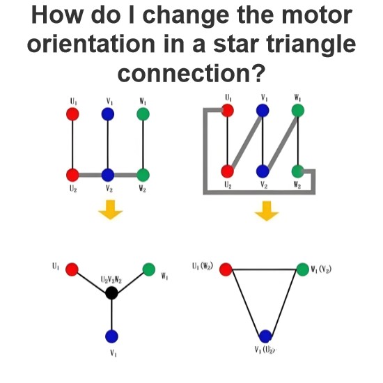
Synchronous Motor Circuit Diagram

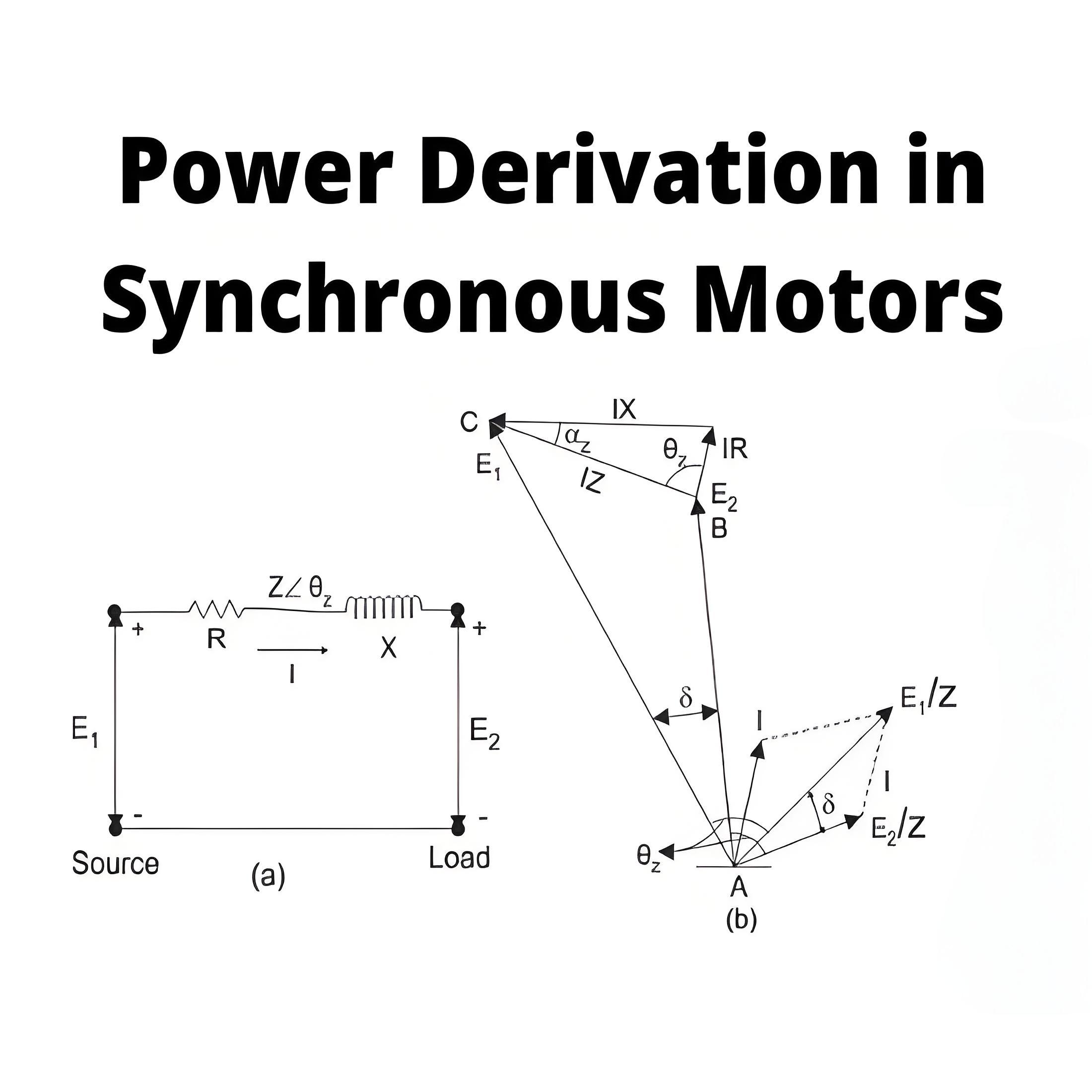
The synchronous motor circuit diagram includes terminal voltage, effective resistance, leakage reactance, fictitious reactance, and synchronous reactance.

Counter EMF

Counter EMF is the voltage induced in the stator winding due to the rotating magnetic field, which opposes the applied voltage.

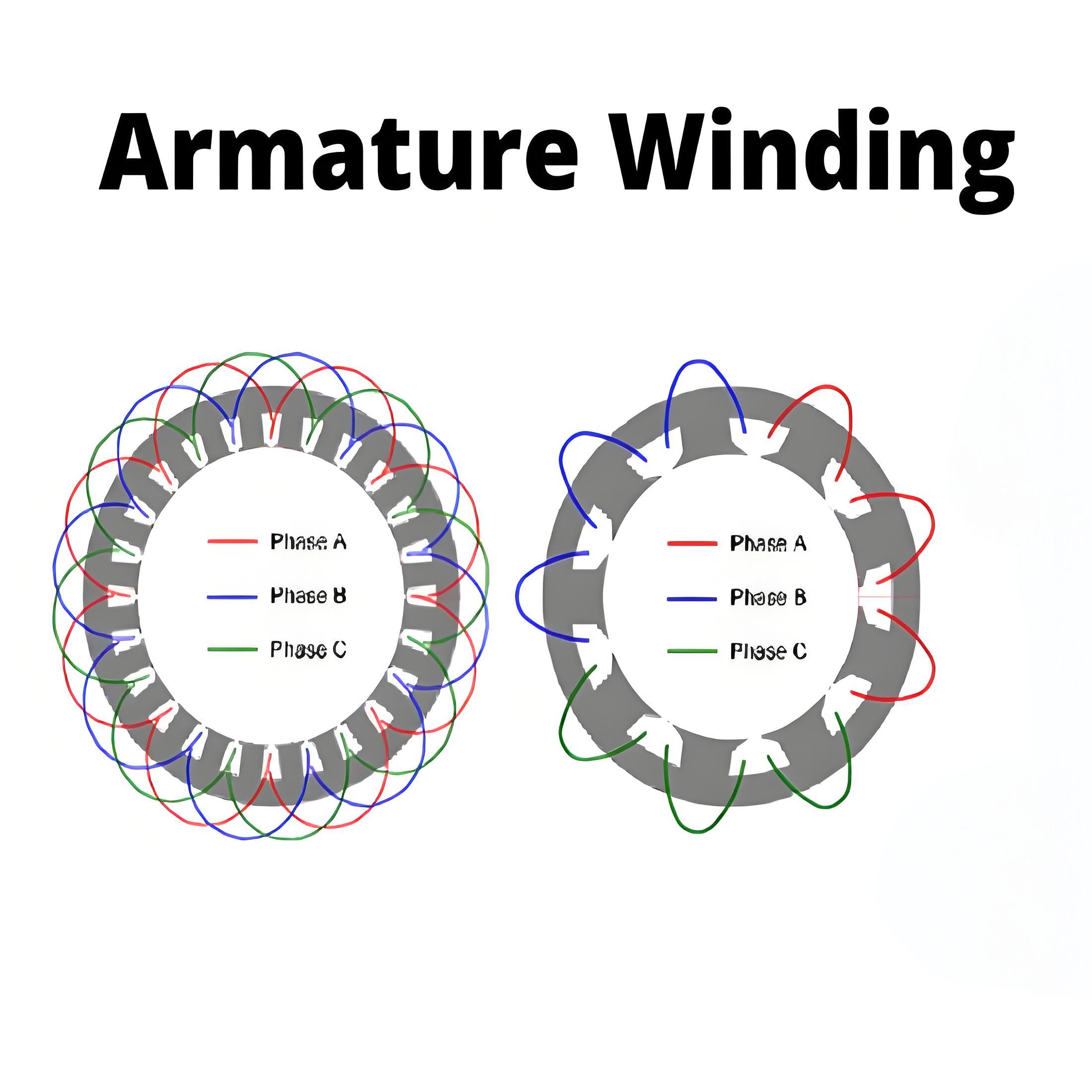
Zero Power Factor Method

This method involves plotting the armature terminal voltage against the field current at zero lagging power factor to measure synchronous reactance.

 3baa8a0646c7f7d6e7f79c01c40de106.jpeg

Y = Terminal voltage

Ia = Armature current

Ra = Armature resistance

XL = Leakage reactance

Eg = Generated voltage per phase

Fa = Armature reaction mmf

Ff = Field mmf

Fr = Resultant emf

Potier Triangle

A graphical representation used to determine synchronous reactance by forming a triangle that represents different voltage drops.

Encyclopedia

The Electricity Encyclopedia is dedicated to accelerating the dissemination and application of electricity knowledge and adding impetus to the development and innovation of the electricity industry.

How do I change the motor orientation in a star triangle connection?
In a Star-Delta or Y-delta connection, changing the direction of the motor can be achieved by changing the phase sequence applied to the motor windings. The direction of the motor depends on the power supply phase sequence, that is, the order in which the three phases of the power supply reach the motor winding. The following are the specific operation steps and principles:Star connection (Star/Y connection)Star connection principle: In a star connection, one end of the three windings is connect
Encyclopedia
09/28/2024
Armature Winding
Armature Winding
Armature winding definitionThe armature winding in an alternator is the arrangement of coils to generate electricity and is essential to its operation.Type of armature windingSingle-phase armature windingSingle-phase armature windings can be centralized or distributed.Centralized armature windingWhen the number of slots on the armature equals the number of poles in the machine, the central winding is used. This winding type provides maximum output voltage, but is not always fully sinusoidal. The
Encyclopedia
08/17/2024
Power Derivation  in Synchronous Motors
Power Derivation in Synchronous Motors
Power Flow in Inductive CircuitsPower flow through an inductive impedance involves voltage sources and a load with a resistor and inductor.Phasor DiagramsPhasor diagrams visually represent voltages and currents in a circuit, helping to understand power conditions.Power Equation of Synchronous GeneratorThe power equation of a synchronous generator relates the voltage, current, and phase angles to determine power output.Maximum Power Output ConditionsMaximum power output in alternators and synchro
Encyclopedia
08/17/2024
What is an Electrical Generator ?
What is an Electrical Generator ?Generator Working PrincipleAn electric generator works by moving a conductor through a magnetic field, inducing an electromotive force (EMF) based on Faraday’s law of electromagnetic induction.Fleming’s Right Hand RuleThis rule determines the direction of EMF, using thumb for motion, first finger for magnetic field, and second finger for EMF direction.AC vs. DC GeneratorsAC generators use slip rings to maintain the alternating nature of the generated current, whe
Encyclopedia
08/17/2024
Inquiry
Download
Experts Electrical is dedicated to serving the personnel in the global power industry.
Join Experts Electrical, not only can you discover power equipment and power knowledge, but also canhnd like - minded friends!