What is a Rogowski Coil?
What is a Rogowski Coil?
Rogowski Coil Definition
A Rogowski coil is defined as an electrical device that measures alternating current (AC) and high-speed transient or pulsed currents.
Rogowski Coil Characteristic
A Rogowski coil is an evenly wounded coil with N number of turn and constant cross-section area A. There is no metal core in a Rogowski coil. The end terminal of the coil is returned through the central axis of the coil to another end. Therefore, both terminals are at the same end of the coil.
Working Principle
Rogowski coils operate based on Faraday’s law, similar to AC current transformers (CTs). In CTs, the voltage induced in the secondary coil is proportional to the current in the conductor. The difference between Rogowski coils and AC current transformers is in the core. In Rogowski coils, an air core is used and in the current transformer, a steel core is used.
When current passes through the conductor, it will create a magnetic field. Due to an intersection with a magnetic field, a voltage is induced between the terminals of the Rogowski coil.
The magnitude of voltage is proportional to the current passes through the conductor. Rogowski coils are close pathed. Generally, the output of Rogowski coils is connected with the integrator circuit. So, the coil voltage is then integrated to provide an output voltage that is proportional to the input current signal.
Rogowski Coil Integrator
According to components used in integrator, there are two types of integrator;
Passive Integrator
Active Integrator
Passive Integrator
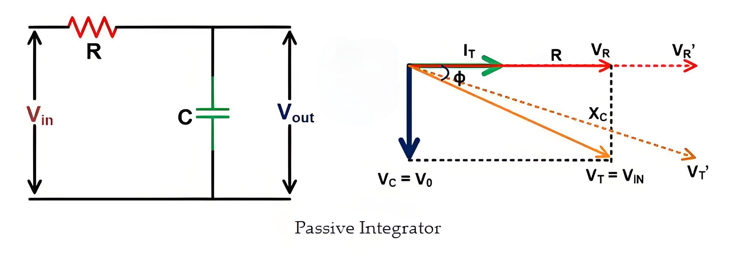
For a large output range of Rogowski coils, the series RC circuit act as an integrator. The value of the acceptable phase error decides the value of Resistance (R) and Capacitance (C).
The relationship between R and C and phase error can be derived from the phasor diagram of the RC network. And it is as shown in the below figure.
In the phasor diagram,
VR and VC represent the voltage drop across the resistor and capacitor,
IT is the net current in the network,
V0 is the output voltage. This voltage is the same as the voltage across the capacitor (VC),
VIN is the input voltage. It is a vector sum of a voltage drop across the resistor and capacitor.
The voltage drop across the resistor is in-phase and a voltage
drop across the capacitor will lag by 90˚ with respect to the net current.
Active Integrator
The RC circuit acts as an attenuator, reducing the voltage across the capacitor. At low current levels, the output voltage can be very low, in microvolts (μV), creating a weak signal for the Analog to Digital Converter (ADC).
This problem can be solved by using an Active Integrator. The circuit of an active integrator is as shown in the below figure.
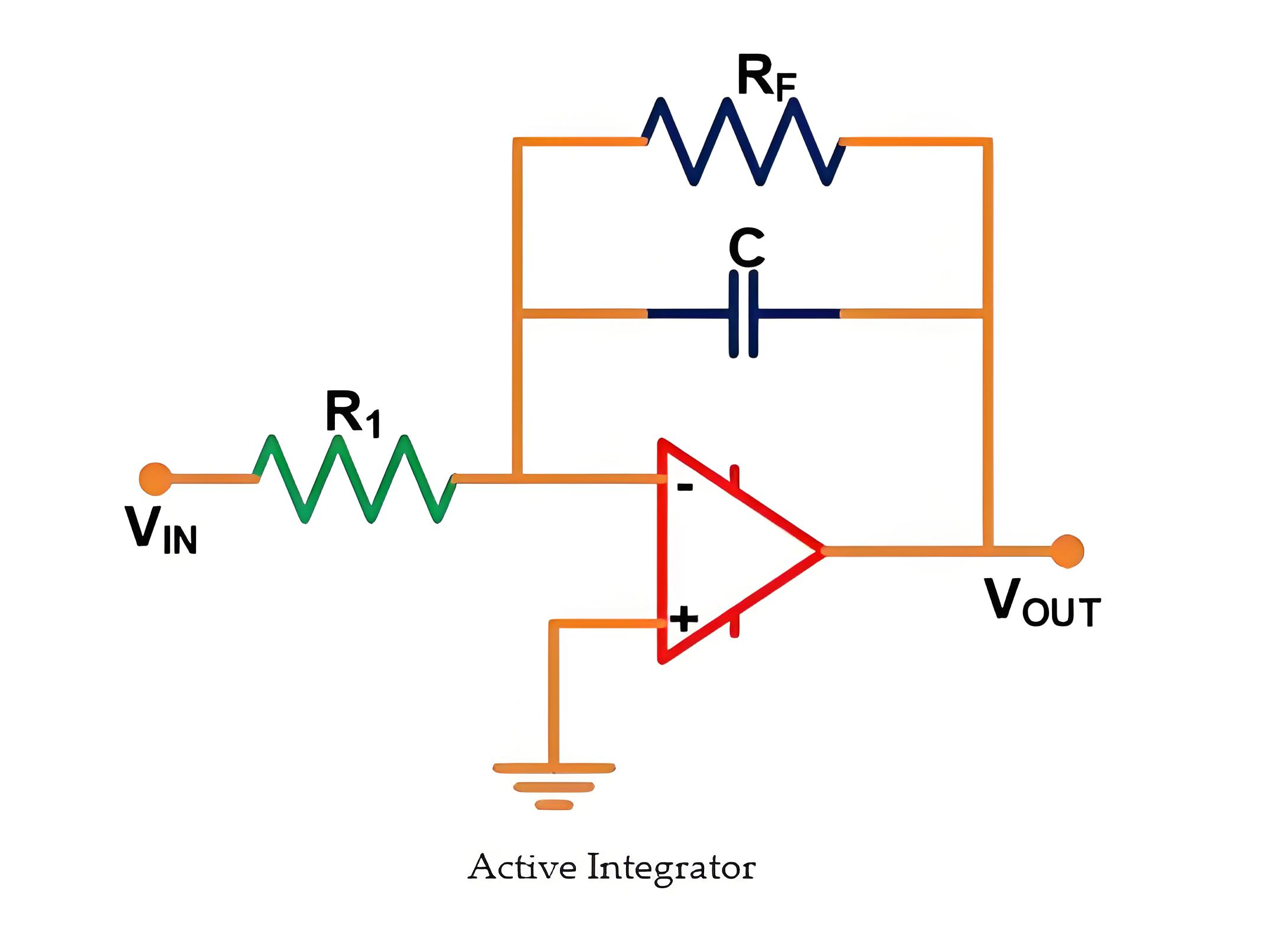
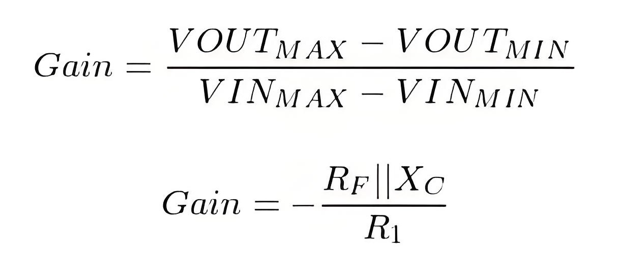
Here, the RC element is in a feedback path of an Amplifier. The gain of the amplifier can be adjusted by using the below equation.
Advantages of Rogowski Coil
It can respond to fast-changing currents.
There is no danger of opening of the secondary coil.
Air is used as the medium, with no magnetic core. This prevents any risk of core saturation.
In this coil, temperature compensation is simple.
Disadvantages of Rogowski Coil
To obtain the current waveform, the output of the coil must be pass through the integrator circuit. It needs a power supply of 3V to 24Vdc.
It cannot measure the DC current.
The Electricity Encyclopedia is dedicated to accelerating the dissemination and application of electricity knowledge and adding impetus to the development and innovation of the electricity industry.
