What is the Equivalent Circuit for an Induction Motor?
What is the Equivalent Circuit for an Induction Motor?
Equivalent Circuit Definition
The equivalent circuit of an induction motor shows its internal parameters like losses using inductors and resistors. The induction motor always runs below the synchronous or full load speed and the relative difference between the synchronous speed and speed of rotation is known as slip which is denoted by s.
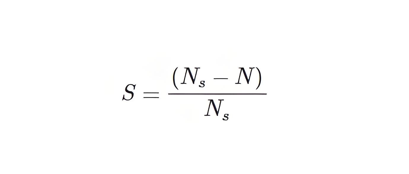
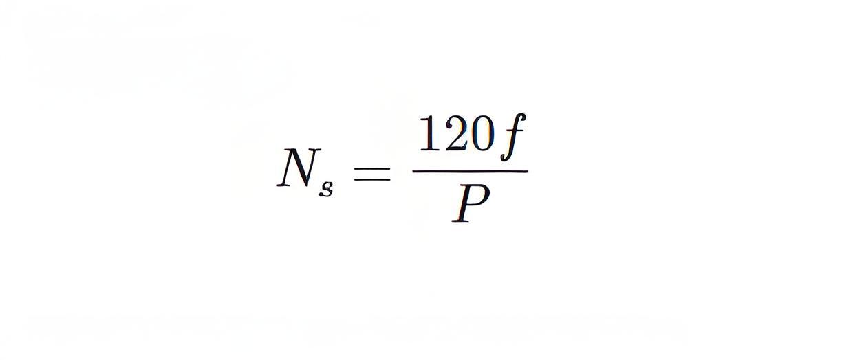
Where, Ns is synchronous speed of rotation which is given by-Where, f is the frequency of the supply voltage.P is the number of poles of the machine.
Components of Equivalent Circuit
Includes elements like winding resistance (R1, R2), inductance (X1, X2), core loss (Rc), and magnetizing reactance (XM).
Exact Equivalent Circuit
Provides detailed parameters, showing power and losses in the motor.
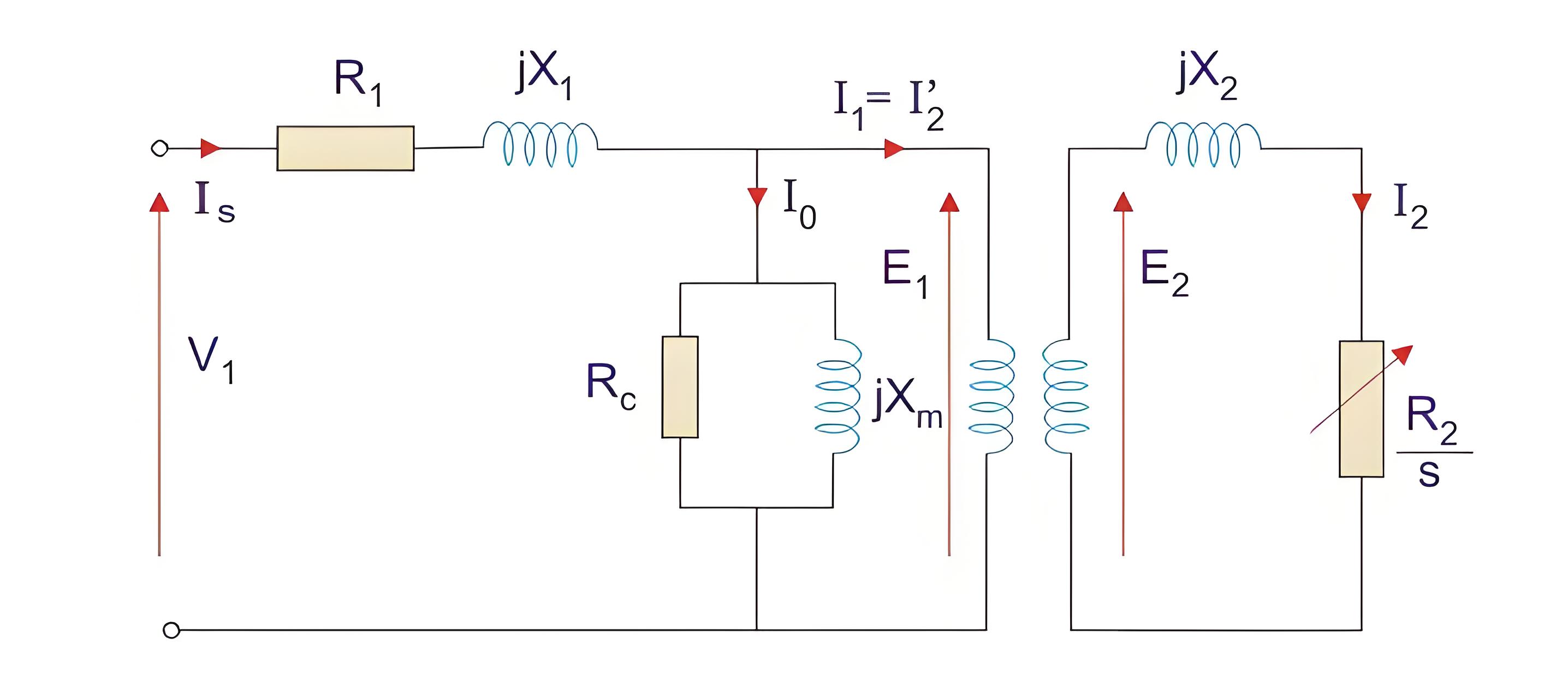
Here, R1 is the winding resistance of the stator.
X1 is the inductance of the stator winding.
Rc is the core loss component.
XM is the magnetizing reactance of the winding.
R2/s is the power of the rotor, which includes output mechanical power and copper loss of rotor.
Approximate Equivalent Circuit
Simplifies analysis by shifting the shunt branch but is less accurate for smaller motors.
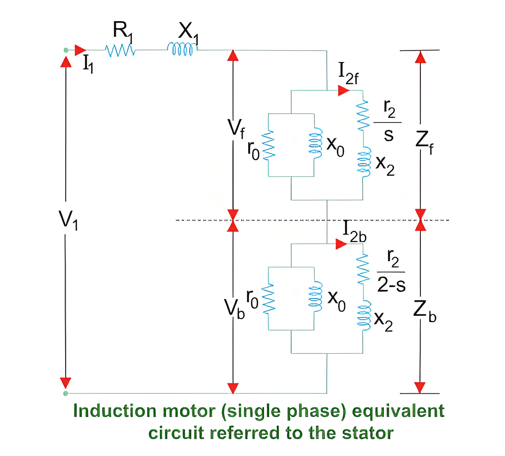
Single-Phase Induction Motor
Uses the double revolving field theory to explain its equivalent circuit, accounting for forward and backward rotating fields.
The Electricity Encyclopedia is dedicated to accelerating the dissemination and application of electricity knowledge and adding impetus to the development and innovation of the electricity industry.

