AC High voltage Air Break Disconnector Switch Routine Test According to IEC 62271-102 Standard
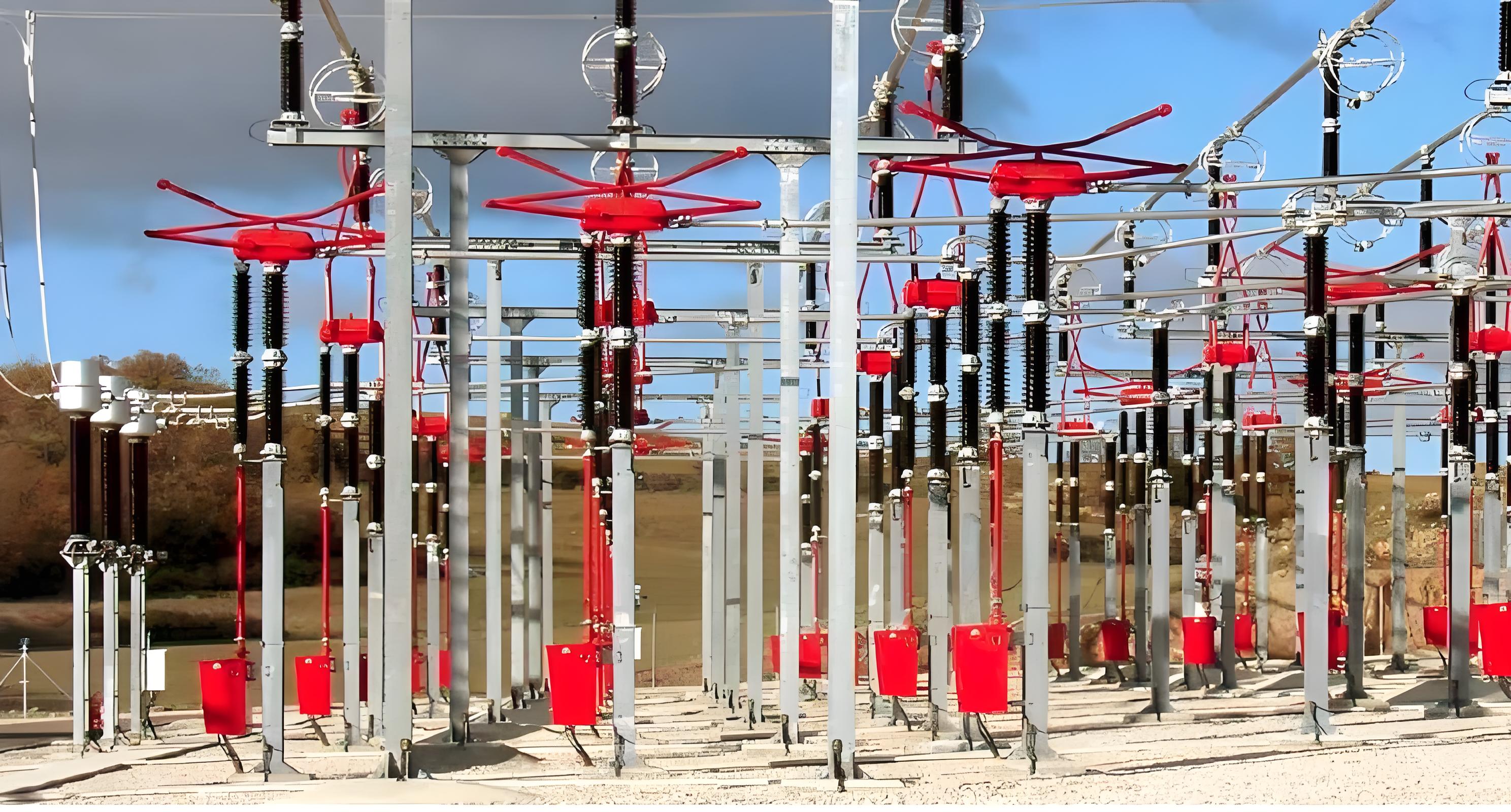
High Voltage Air-Break Disconnectors and Earthing Switches: Function, Types, and Routine Testing
Function of High Voltage Air-Break Disconnectors
High voltage air-break disconnectors play a critical role in high voltage power systems by providing electrical and visible isolation between different parts of the system. This isolation is essential for both normal day-to-day operations and maintenance or repair activities. The two primary forms of isolation are:
- Isolation for Normal Operation:During normal operation, certain components of the power system, such as shunt reactors, may only be required during light load periods. These components can be switched out using circuit breakers and then isolated using disconnectors when they are not needed (e.g., during peak load periods). This allows for efficient management of the power system's resources.
- Isolation for Maintenance and Repair:When transmission lines, transformers, circuit breakers, or other station equipment require maintenance or repair, it is crucial to isolate these components from the rest of the system to ensure safety. Air-break disconnectors provide a visible break in the circuit, allowing workers to confirm that the section of the system they are working on is de-energized and safe to access.
Types of High Voltage Air-Break Disconnectors and Earthing Switches
High voltage air-break disconnectors and earthing switches come in various types and mounting arrangements. The four most commonly used types are:
- Vertical Break Type:In this type, the moving contact moves vertically to open or close the disconnector. This design is suitable for applications where space is limited, as it requires less horizontal clearance.
- Centre Side Break Type:The moving contact in this type breaks at the center of the disconnector, with the contacts on either side remaining stationary. This design provides a clear visual indication of the open position and is often used in switchgear applications.
- Double Side Break Type:This type has moving contacts that break on both sides of the disconnector. It provides a more robust isolation and is commonly used in high-voltage substations where reliable isolation is critical.
- Pantograph Type:The pantograph type uses a scissor-like mechanism to move the contacts apart. This design is particularly useful for high-voltage applications where large distances between contacts are required to ensure proper isolation.
Routine Testing of High Voltage Disconnectors and Earthing Switches
Routine testing is performed to ensure that high voltage disconnectors and earthing switches meet the required standards and specifications. These tests are designed to reveal any faults in materials or construction without impairing the properties or reliability of the equipment. According to IEC 62271-1 and IEC 62271-102 standards, the following routine testing items are typically conducted:
Dielectric Test on the Main Circuit:A dry, short-duration power-frequency test with a frequency of 50 or 60 Hz is applied to the main circuit. The test voltage is specified in the relevant IEC standards and should be adjusted based on the altitude factor.
The purpose of this test is to verify the insulation strength of the disconnector and ensure that it can withstand the rated voltage without breakdown. The test voltage values are provided in the standard tables, and the altitude factor must be considered to account for the reduced dielectric strength of air at higher altitudes.
- Mechanical Operation Test:This test ensures that the disconnector can operate correctly under normal operating conditions. It checks the smoothness of the opening and closing mechanisms, as well as the alignment of the contacts. The test also verifies that the disconnector can handle the specified number of operations without failure.
- Temperature Rise Test:This test measures the temperature rise of the disconnector under rated current conditions. The goal is to ensure that the temperature rise does not exceed the permissible limits, which could lead to overheating and potential damage to the equipment.
- Short-Circuit Withstand Test:This test evaluates the disconnector's ability to withstand the thermal and electrodynamic effects of a short-circuit fault. Although disconnectors are not designed to interrupt short-circuits, they must be able to remain intact and safely isolate the faulted section of the system.
- Earthing Switch Operation Test:For earthing switches, a separate test is conducted to ensure that the switch can properly connect the system to ground. This test checks the reliability of the earthing function, which is critical for safety during maintenance and repair operations.
- Insulation Resistance Test:This test measures the insulation resistance between live parts and earth to ensure that there is no leakage current. A high insulation resistance indicates that the disconnector's insulation is in good condition.
- Visual Inspection:A thorough visual inspection is performed to check for any physical damage, corrosion, or wear on the disconnector and its components. This inspection helps identify any issues that could affect the performance or safety of the equipment.
Importance of Routine Testing
Routine testing is essential to ensure that high voltage disconnectors and earthing switches are functioning correctly and can safely perform their isolation duties. These tests are typically conducted at the manufacturer's facility, but by agreement, they can also be performed on-site. The tests help identify any defects or weaknesses in the equipment before it is installed or put into service, ensuring that the power system operates reliably and safely.
By adhering to the IEC 62271-1 and IEC 62271-102 standards, manufacturers and operators can maintain the integrity and performance of high voltage disconnectors and earthing switches, thereby enhancing the overall safety and efficiency of the power system.
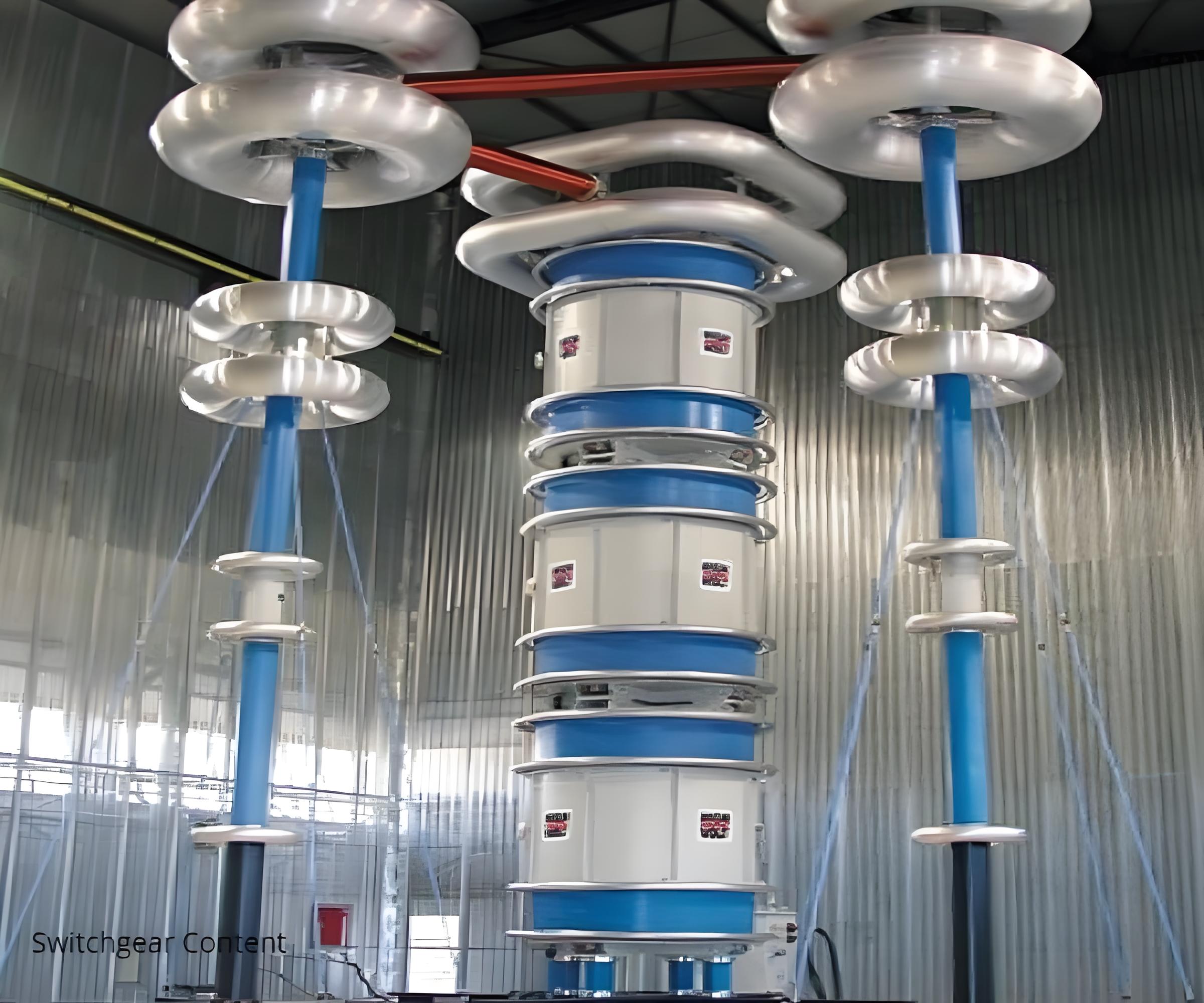
When the insulation of disconnector and earth switch is provided only by solid-core insulators and air at ambient pressure, the power-frequency voltage withstand test may be omitted if the dimensions between the conductive parts – between phases, across open switching devices and between conductive parts and the frame – are checked by dimensional measurements.
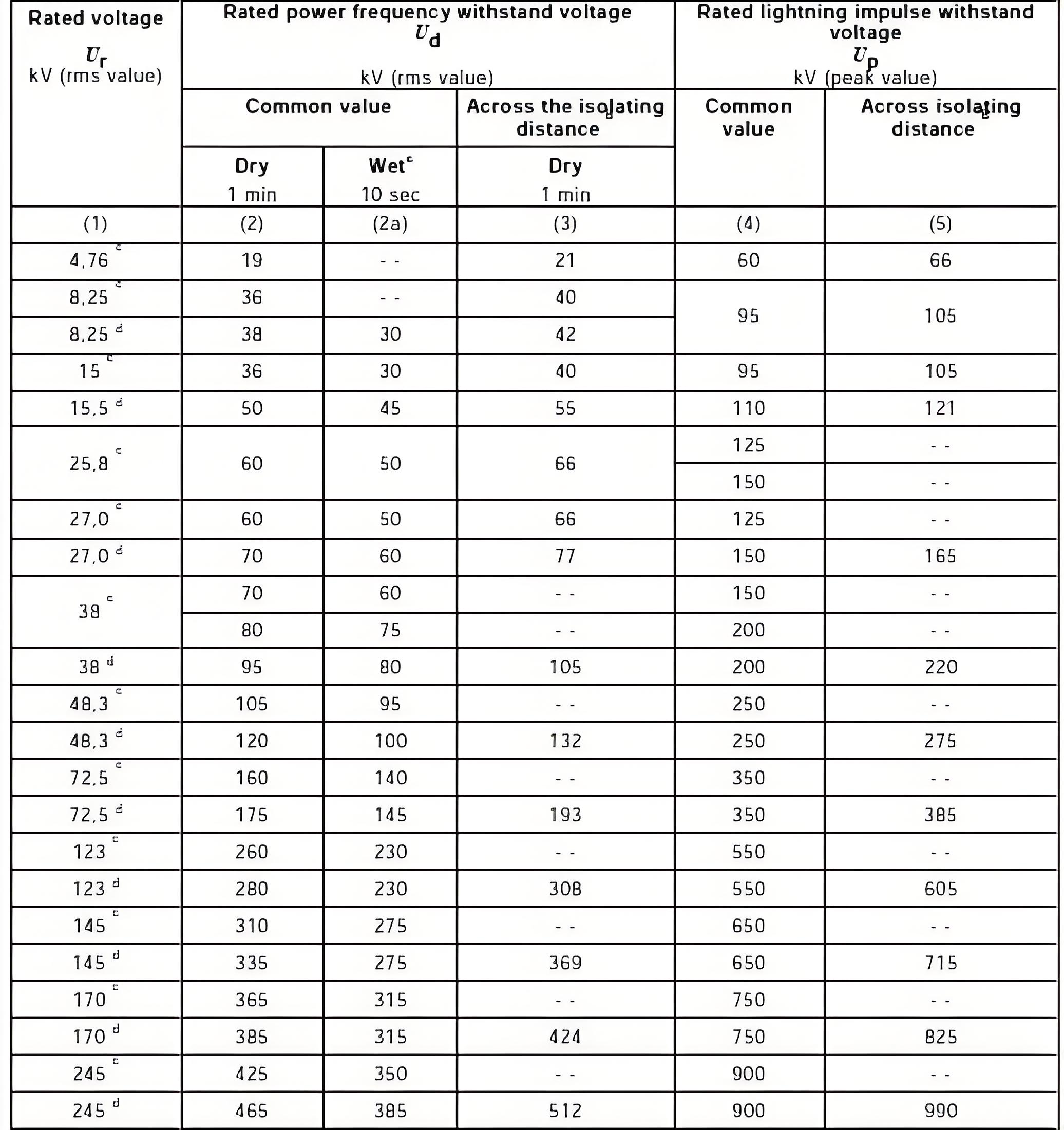
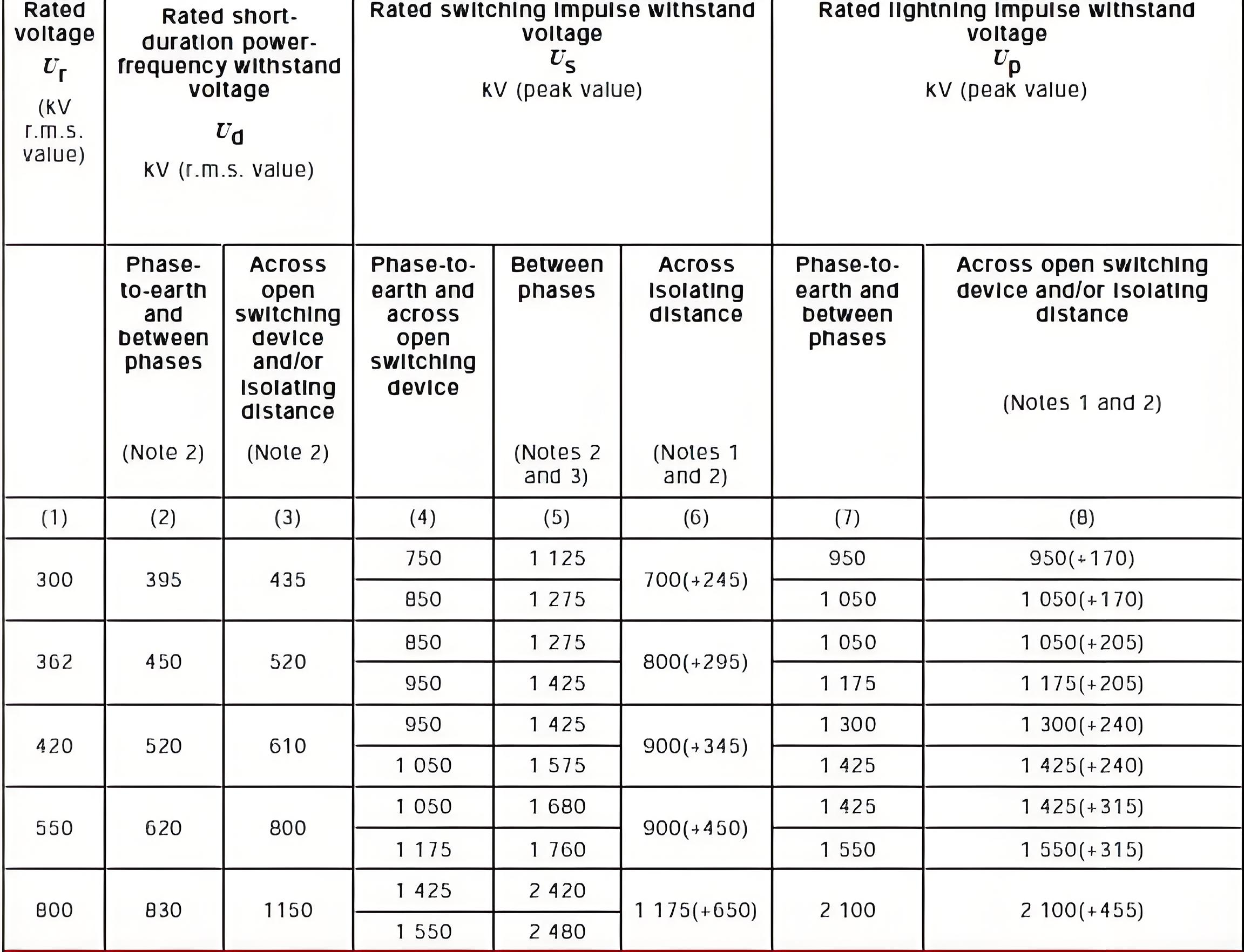
Dielectric Testing of Earthing Switches and Auxiliary/Control Circuits in High Voltage Disconnectors
- Dielectric Test on Earthing Switches
When performing a dielectric test on earthing switches, the test voltage is applied with the earthing switch in the open position. The test is conducted under two specific conditions to ensure proper insulation between different parts of the switch:
Between Adjacent Insulated Terminals (with Bases Earthed):The test voltage is applied between adjacent insulated terminals while the bases of the switch are earthed. This ensures that there is sufficient insulation between the terminals to prevent any accidental short circuits or electrical breakdown.
Between All Insulated Terminals Connected Together (with Bases Earthed):In this condition, all the insulated terminals are connected together, and the test voltage is applied between this group of terminals and the earthed bases. This test checks the overall insulation integrity of the switch, ensuring that there is no leakage current between the terminals and ground.
2. Dielectric Test on Auxiliary and Control Circuits in Operating Mechanism
Inspection and Verification of Conformity
- Material and Assembly Quality:The nature of the materials used in the auxiliary and control circuits, the quality of assembly, the finish, and any protective coatings against corrosion are inspected. This ensures that the components are suitable for their intended use and will not degrade over time.
- Thermal Insulation:A visual inspection is performed to verify the satisfactory installation of thermal insulation. Proper thermal insulation is crucial to prevent overheating and ensure the longevity of the equipment.
- Conductor and Cable Routing:The routing of conductors, cables, and heaters is checked to ensure they are properly installed and do not pose any risk of damage or interference. Resistance checks are also performed on heaters to ensure they are functioning correctly.
Functional Tests
- Low-Voltage Circuit Functionality:A functional test of all low-voltage circuits, including relays, contactors, and interlocking magnets, is conducted to verify that the auxiliary and control circuits operate correctly in conjunction with other parts of the disconnector switch. The interlocking mechanism must also be checked to ensure it functions as intended.
- Protection Against Electrical Shock:Visual inspections are carried out to verify that there is adequate protection against direct contact with the main circuit and that auxiliary and control equipment parts, which may be touched during normal operation, are safely accessible. This ensures that operators are protected from electrical shock.
Dielectric Tests on Auxiliary and Control Circuits
Power Frequency Tests:Only power frequency tests are performed on the auxiliary and control circuits. The test voltage is either 1 kV or 2 kV with a duration of 1 second at a frequency of 50 or 60 Hz. This test ensures that the insulation of the low-voltage circuits can withstand the rated voltage without breakdown.
3. Measurement of the Resistance of the Main Circuit
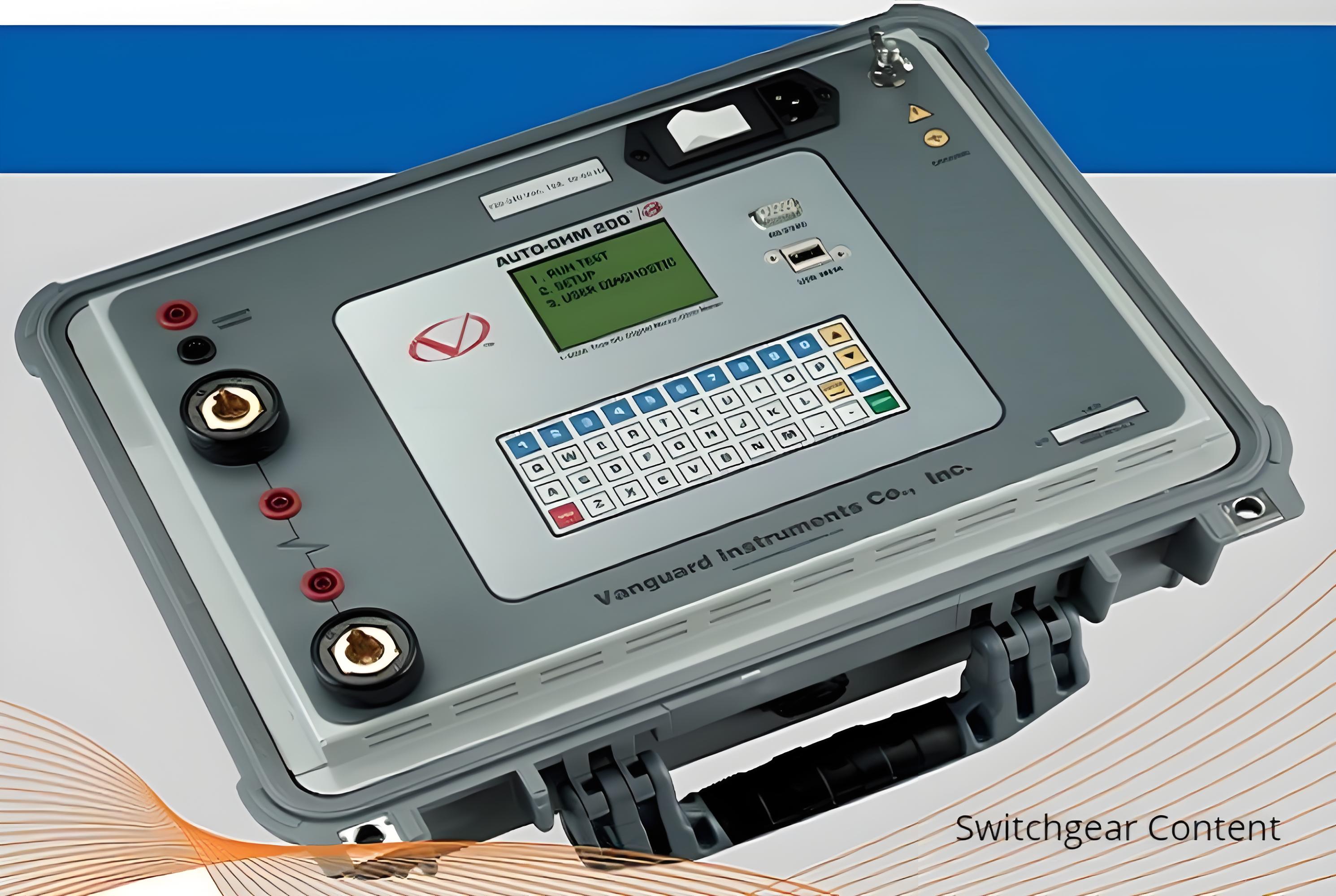
For the routine test, the DC voltage drop or resistance of each pole of the main circuit is measured under conditions as similar as possible to those used during the type test. Specifically:The ambient air temperature and points of measurement should be as close as possible to those during the type test.
The measured resistance should not exceed 1.2 × Ru, where Ru is the resistance measured before the temperature-rise test. This ensures that the resistance of the main circuit remains within acceptable limits, indicating that the contacts are in good condition and the circuit can carry the rated current without excessive heating.
4. Design and Visual Checks
The disconnector and earthing switches must undergo thorough design and visual inspections to ensure they comply with the purchase specification. This includes:
- Verification of Compliance: Ensuring that all components, materials, and construction meet the specified requirements as outlined in the purchase order or contract.
- Inspection of Components: Checking for any visible defects, such as cracks, corrosion, or improper assembly, which could affect the performance or safety of the equipment.
- Labeling and Markings: Verifying that all necessary labels, markings, and identification tags are present and legible, including voltage ratings, operating instructions, and safety warnings.
5. Mechanical Operating Tests
Mechanical operating tests are conducted to ensure that the disconnectors or earthing switches function correctly within the specified voltage and supply pressure limits of their operating mechanisms. These tests are performed without voltage on or current flowing through the main circuit. The following aspects are verified:
Operating Mechanism Performance
- Angle of Operating Mechanism Output Shaft:The angle of rotation of the operating mechanism's output shaft is measured to ensure it aligns with the designed specifications. This ensures that the contacts move to the correct positions during opening and closing operations.
- Measuring Torque of Operating Mechanism Output:The torque required to operate the mechanism is measured to ensure it falls within the specified limits. Excessive torque can indicate mechanical issues, while insufficient torque may lead to incomplete operation.
- Operating Mechanism Motor Current:The current drawn by the motor during operation is recorded to verify that it remains within the acceptable range. Abnormal current levels can indicate problems with the motor or the electrical supply.
- Operating Times:The time taken for the disconnector or earthing switch to complete a full cycle (close-open) is measured. This ensures that the device operates within the required time limits, which is critical for system coordination and protection.
Operating Cycles
The following operating cycles are performed to test the reliability and endurance of the disconnector or earthing switch:
- 10 Close-Open Cycles at Minimum Supply Voltage (85%):The disconnector or earthing switch is operated 10 times at 85% of the nominal supply voltage to ensure it functions correctly under low-voltage conditions.
- 10 Close-Open Cycles at Maximum Supply Voltage (110%):The disconnector or earthing switch is operated 10 times at 110% of the nominal supply voltage to verify its performance under high-voltage conditions.
- 50 Close-Open Cycles at Nominal Supply Voltage (100%):The disconnector or earthing switch is operated 50 times at the nominal supply voltage to test its long-term reliability and endurance under normal operating conditions.
During these operating cycles, the following characteristics are recorded or evaluated:
- Operating Time: The time taken for each close-open cycle is measured to ensure consistency.
- Maximum Energy Consumption: The energy consumed by the operating mechanism during each cycle is recorded to verify that it remains within the specified limits.
- Manual Operation (if applicable): For disconnectors with manual mechanisms, the maximum force required to operate the device is recorded. This ensures that the manual operation is within safe and ergonomic limits.
Auxiliary Contacts and Position Indicating Devices
The satisfactory operation of auxiliary contacts and position indicating devices (if any) is verified. These components provide critical feedback to the control systems and must function reliably to ensure proper system operation.
Post-Test Inspection
After completing the mechanical operating tests, no parts of the disconnector or earthing switch should be damaged. The device should remain in good working condition, with no signs of wear, deformation, or malfunction.
Main Circuit Resistance Measurement
The resistance of the main circuit is measured both before and after the mechanical endurance test. The resistance should not vary by more than 20% from the value measured before the test. This ensures that the contacts have not deteriorated or become misaligned during the testing process, which could affect the electrical performance of the device.
Special Considerations for High-Voltage Equipment
For disconnectors and earthing switches with a rated voltage of 52 kV and above, the mechanical operating routine tests may be performed on sub-assemblies. This allows for more manageable testing procedures while still ensuring that the overall performance of the device meets the required standards.
Conclusion
By conducting these comprehensive design and visual checks, as well as mechanical operating tests, manufacturers and operators can ensure that high-voltage disconnectors and earthing switches are reliable, safe, and capable of performing their intended functions under various operating conditions. These tests help identify any potential issues early in the process, ensuring that the equipment is ready for installation and service in high-voltage power systems.

