Phenomena created during switching of no-load transformers by AIS high voltage disconnect switch
Introduction to High-Voltage Isolators
- Difference Between High-Voltage Circuit Breakers and Earthing Switches
High-Voltage Circuit Breaker (Circuit Breaker) and Earthing Switch are two different mechanical switching devices, each playing a crucial role in power systems.
- High-Voltage Circuit Breaker: It is primarily used to indicate whether a circuit is open or closed. The circuit breaker has the capability to interrupt current, allowing it to cut off large currents under live conditions and maintain stability when the contact points are separated and a recovery voltage is established. High-voltage circuit breakers are typically used to protect power systems from faults such as short circuits and overloads.
- Earthing Switch: Its main function is to ground various parts of a circuit, including equipment, ensuring safe contact. An earthing switch does not have the ability to interrupt current, so it cannot be used to cut off load currents. It is usually used in conjunction with a high-voltage circuit breaker to ensure that, after the circuit breaker is opened, all parts of the circuit can be reliably grounded to prevent accidental electric shock.
- Operational Limitations of AIS High-Voltage Circuit Breakers
In Air Insulated Switchgear (AIS), a high-voltage circuit breaker cannot interrupt current while conducting or after the contacts are separated and a recovery voltage is established between them. This means that if the circuit breaker operates under live conditions, it can only effectively interrupt small currents. Specifically, when the rated voltage appears across the contacts, the circuit breaker can interrupt small currents but cannot handle high currents or heavy loads.
- Function of Earthing Switches
The primary role of an earthing switch is to ground various parts of a circuit, ensuring safety during maintenance or inspection. It can be used in conjunction with a high-voltage circuit breaker or independently. By grounding the circuit, the earthing switch effectively eliminates static charge accumulation, prevents accidental electric shock, and provides safety for subsequent maintenance work.
Overview of Capacitive and No-Load Transformer Switching
- Capacitive Current Switching Capability of High-Voltage Circuit Breakers
According to IEC standards, high-voltage circuit breakers are not specifically designed for interrupting fault currents, but since they operate under live conditions, they are expected to interrupt small currents. The IEC definition of isolators (disconnectors) states that a circuit breaker (isolator) can open or close a circuit where negligible current is interrupted or connected, or where the voltage between the terminals of the circuit breaker's poles does not change.
Although not explicitly stated, this description can be interpreted to refer to small capacitive charging currents and loop switching (also known as parallel switching), which in specific applications are called bus transfer switches. IEC 62271-102 confirms this and sets an upper limit of 0.5 A for "negligible" capacitive charging currents, with higher values requiring agreement between the user and the manufacturer.
- Rated Bus Transfer Current
According to IEC 62271-102, the rated bus transfer current is specified as follows:
- For voltage levels 52 kV < Ur < 245 kV, the bus transfer current is 80% of the circuit breaker's rated normal current, but limited to 1600 A.
- For voltage levels 245 kV ≤ Ur ≤ 550 kV, the bus transfer current is 60% of the circuit breaker's rated normal current.
- For voltage levels Ur > 550 kV, the bus transfer current is 80% of the circuit breaker's rated normal current, but limited to 4000 A.
- Application of No-Load Transformer Switching
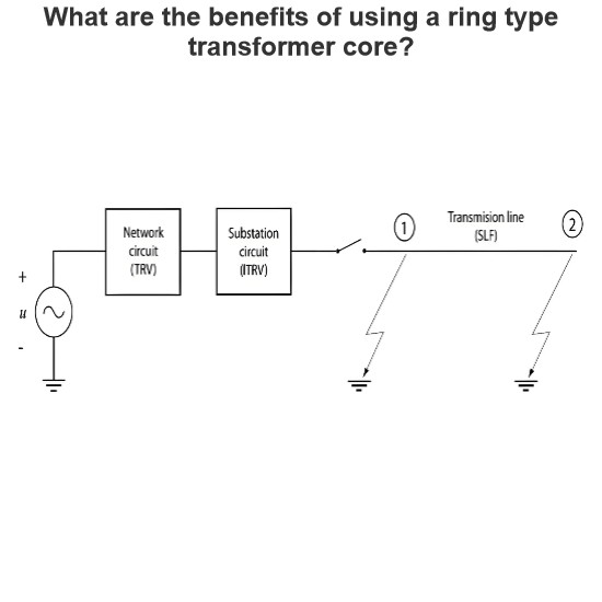
In practice, especially in North America, air circuit breakers are commonly used for switching no-load transformers. The magnetizing current of a no-load transformer is typically very low, usually 1 A or less. In this case, the transformer can be represented as a series RLC circuit (as shown in Figure 1), with related oscillations being underdamped, and the amplitude factor being 1.4 or less per unit.
- Loop Switching in Parallel Transmission Loops
Another common practice is to extend bus transfer to switching between parallel transmission loops, although the current is lower due to higher loop impedance. This approach can effectively reduce arc generation and voltage fluctuations during switching.
- Application of Auxiliary Switching Devices
A widely used practice in North America, but less common in other regions, is the addition of auxiliary switching devices to mitigate the severity of switching events. For example, these devices can minimize the occurrence of restrikes or achieve higher breaking capacity. The use of auxiliary switching devices can enhance system reliability and safety, especially when handling high currents or complex circuits.
No-Load Transformer Switching Using AIS High-Voltage Isolators
For no-load transformer switching in the 72.5–245 kV range, AIS high-voltage isolators are commonly used. Since the magnetizing current of a no-load transformer is typically very low (usually 1 A or less), isolators can safely perform the switching operation. The transformer can be simplified as a series RLC circuit, with related oscillations being underdamped, and the amplitude factor being 1.4 or less per unit.
In this scenario, the primary task of the isolator is to ensure that the transformer's magnetizing current does not cause significant arcing or voltage fluctuations during switching. Through proper design and operation, AIS high-voltage isolators can effectively accomplish this task, ensuring the safe and stable operation of the power system.

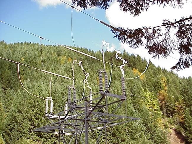
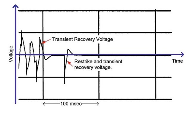
A trace from an actual field-switching event is shown in Fig. 2.
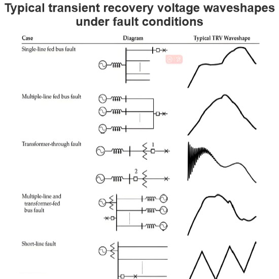
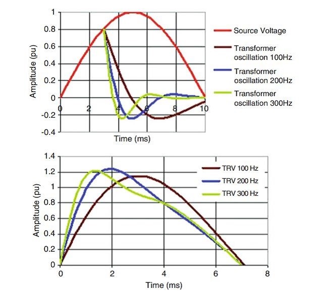
The transient recovery voltage (TRV) across the disconnecting switch is thus the difference between the source voltage and the transformer-side oscillation as illustrated in Fig. 3.
Current Interruption: A Dielectric Event
Current interruption fundamentally occurs when the gap between the contacts becomes sufficiently large to withstand the transient recovery voltage (TRV). This process is inherently a dielectric event, where the insulation strength of the air or vacuum between the contacts surpasses the applied voltage, effectively quenching the arc and interrupting the current flow.
Interrupting the Magnetizing Current of a No-Load Transformer
Interrupting the magnetizing current of a no-load transformer is a repetitive open-close event that can result in multiple restrikes. Each restrike can induce surge currents, which prolong the arc duration, extend the overall switching time, and cause wear on the arc contacts. The repeated nature of these events can lead to significant stress on the switching equipment and potentially degrade its performance over time.
To mitigate these effects, it is crucial to ensure that the switching device is capable of handling the specific characteristics of the magnetizing current, such as its inrush behavior and the associated transient voltages. Proper design and selection of the switching equipment, along with the use of auxiliary devices like surge arresters or damping resistors, can help reduce the likelihood of restrikes and minimize the impact on the system.

