Auxiliary contact in switchgears
Auxiliary contacts are essential components in circuit breakers and switchgear, providing critical functionality for control and indication. Here's a breakdown of their purpose and operation:
Purpose of Auxiliary Contacts:
-
Breaker Trip & Closing Control:
-
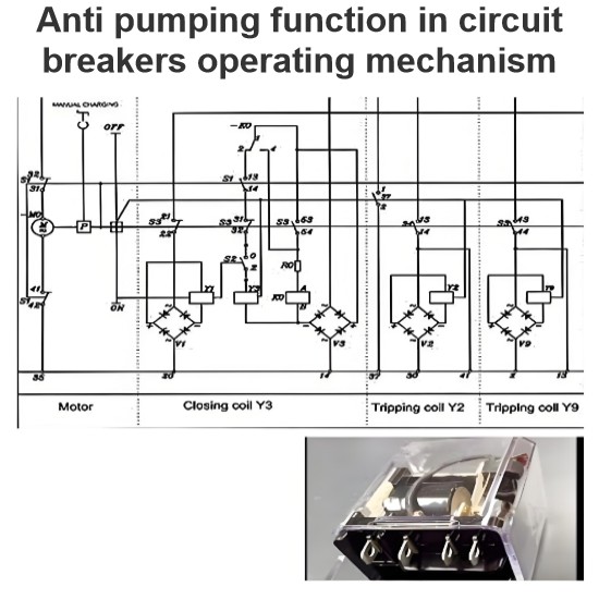
Auxiliary contacts are used in control circuits to manage the supply to the trip coil and closing coil, ensuring proper operation of the circuit breaker.
-
-
Breaker ON/OFF Indication:
-
These contacts provide signals to indicate whether the breaker is in the ON (closed) or OFF (open) position.
-
-
Integration with Relays and SCADA:
-
Auxiliary contacts are connected to devices like the Trip Circuit Supervision (TCS) relay, busbar relay, and SCADA systems for monitoring and control purposes.
-
-
Customer Use:
-
Contacts not used in control circuits are typically made available to customers for custom applications.
-
Types of Contacts:
-
NO (Normally Open) Contact:
-
Open when the device is not energized or in its default state.
-
Closes when the device is energized or activated.
-
-
NC (Normally Closed) Contact:
-
Closed when the device is not energized or in its default state.
-
Opens when the device is energized or activated.
-
-
NOC (Normally Open-Closed) Contact (Change-Over Contact):
-
A combination of NO and NC contacts with a common backside.
-
When the device changes position, the NO contact closes, and the NC contact opens simultaneously.
-
Operation of Auxiliary Switch:
-
When the auxiliary switch operates, its contacts change their status:
-
Open contacts become closed.
-
Closed contacts become open.
-
-
This change in status is used for various control and indication functions in the circuit breaker.
Typical Quantities of Auxiliary Contacts:
-
Auxiliary switches are often provided in standard configurations, such as:
-
12 NO + 12 NC
-
18 NO + 18 NC
-
20 NO + 20 NC
-
Circuit Diagram Representation:
-
In the circuit diagram, the auxiliary switch is typically shown with its NO, NC, and NOC contacts, illustrating how they interact with the breaker's operating mechanism.


