Principle of controlled switching (CS) in circuit breaker

Edwiin
01/21/2025
Controlled Switching (CS) Method
Controlled Switching (CS) is a technique used to eliminate harmful transients by precisely timing the switching operations of circuit breakers (CBs). The closing or opening commands to the CB are delayed in such a way that the contacts make or separate at an optimal phase angle, minimizing transient effects.
Key Principles:
- Voltage Zero Crossing for Closing: To avoid switching transients, the moment of contact closure should ideally occur at the voltage zero crossing point. This ensures that the current starts flowing when the voltage is at its minimum, reducing inrush currents and associated transients.
- Bypassing Protection Commands: When controlled opening is applied, it is crucial that all protection trip commands, especially those triggered during fault interruptions, bypass the controlled switching controller. This ensures that the system can quickly respond to faults without delay.
- Example Scenario: Energizing a Capacitor Bank
- Input Command: When a capacitor bank needs to be energized, an input command is sent to the controlled switching controller.
- Reference Time Instant: The controller determines a reference time instant based on the phase angle of the busbar voltage.
- Waiting Time Calculation: After calculating an internally generated waiting time, the controller issues a closing command to the CB.
- Closing Command Timing: The exact timing of the closing command is determined by considering both the predictable make time of the CB and the target point for making (typically the voltage zero crossing).
- These parameters are pre-programmed into the controller.
- Minimizing Transients: The CB then closes at the correct time instant, thereby minimizing switching transients.
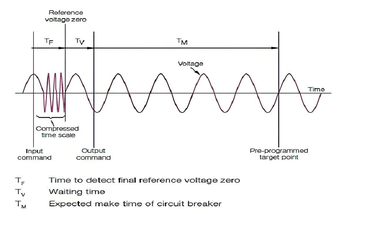
Time Sequence in Controlled Switching
The following steps outline the sequence of events in controlled switching for a single phase of a circuit breaker:
- Initial Command: An input command is received to either close or open the CB.
- Phase Angle Detection: The controller detects the phase angle of the busbar voltage.
- Waiting Period: The controller calculates and waits for the appropriate internal delay.
- Closing Command Issued: Once the calculated waiting period elapses, the controller sends a closing command to the CB.
- Contact Closure: The CB makes contact at the predetermined optimal time (voltage zero crossing), minimizing transients.
Visual Representation
A diagram would typically show the time sequence involved in controlled switching, highlighting the relationship between the busbar voltage waveform, the internal waiting time, and the precise moment of contact closure.
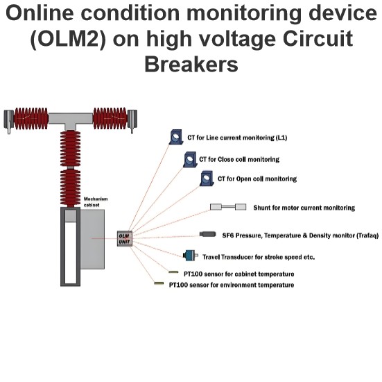
Online condition monitoring device (OLM2) on high voltage Circuit Breakers
This device is capable of monitoring and detecting various parameters according to the specifications outlined:SF6 Gas Monitoring:Utilizes a specialized sensor for measuring SF6 gas density.Capabilities include measuring gas temperature, monitoring SF6 leak rates, and calculating the optimal date for refilling.Mechanical Operation Analysis:Measures operational times for closing and opening cycles.Evaluates primary contacts separation speed, damping, and contact overtravel.Identifies signs of mec
Edwiin
02/13/2025
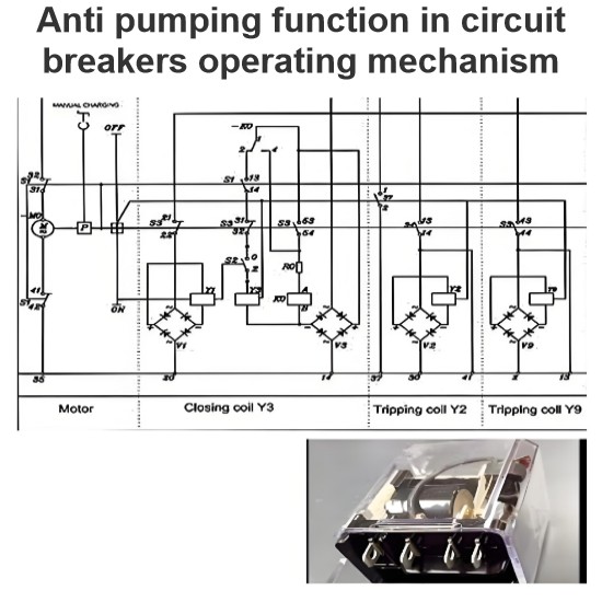
Anti pumping function in circuit breakers operating mechanism
The anti - pumping function stands as a crucial characteristic of control circuits. In the absence of this anti - pumping function, assume that a user connects a maintained contact within the closing circuit. When the circuit breaker is closed onto a fault current, the protective relays will promptly trigger a tripping action. However, the maintained contact in the closing circuit will attempt to close the breaker (once again) onto the fault. This repetitive and dangerous process is referred to
Edwiin
02/12/2025

Ageing phenomena of current pass blades in high voltage disconnector switch
This failure mode has three primary origins:Electrical Causes: The switching of currents, such as loop currents, can lead to localized wear. At higher currents, an electric arc may burn at a specific spot, increasing the local resistance. As more switching operations occur, the contact surface wears down further, causing an increase in resistance.Mechanical Causes: Vibrations, often due to wind, are the main contributors to mechanical aging. These vibrations cause abrasion over time, leading to
Edwiin
02/11/2025
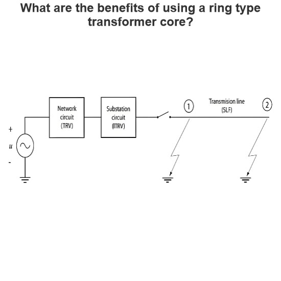
Initial Transient Recovery Voltage (ITRV) for high voltage circuit breakers
Transient Recovery Voltage (TRV) stress similar to that encountered during a short-line fault can also occur due to the busbar connections on the supply side of a circuit breaker. This specific TRV stress is known as Initial Transient Recovery Voltage (ITRV). Given the relatively short distances involved, the time to reach the first peak of ITRV is typically less than 1 microsecond. The surge impedance of the busbars within a substation is generally lower compared to that of overhead lines.The f
Edwiin
02/08/2025


