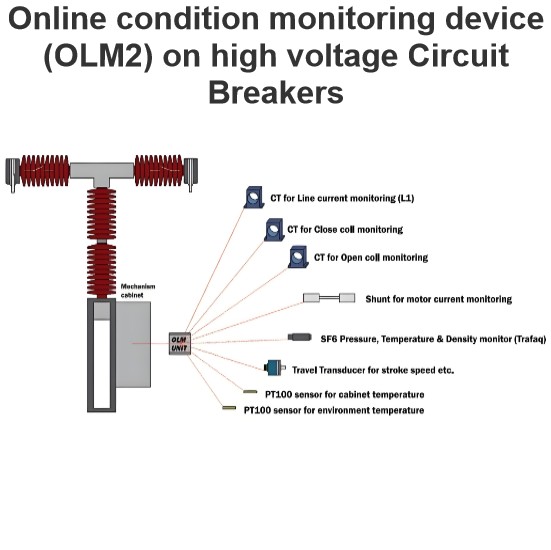
Dielectric combined voltage tests (BIAS test) on circuit breakers

Dielectric Bias Testing of High-Voltage Circuit Breakers
Dielectric bias testing is a critical procedure used to evaluate the insulation performance of high-voltage circuit breakers (CBs) under conditions that simulate real-world voltage stresses. In this test, the circuit breaker is subjected to two separate voltages simultaneously: a power frequency (PF) voltage and either a switching (SW) impulse or a lightning impulse (LI). This combination of voltages mimics the actual voltage conditions that an open circuit breaker may experience during operation.
Test Setup and Conditions
-
Power Frequency (PF) Voltage:
- Applied at one terminal (Terminal A).
- For SW bias tests, the PF voltage corresponds to the rated phase-to-ground voltage of the system. This reflects real-world conditions where switching overvoltages often occur near the peak of the power frequency voltage wave.
- For LI bias tests, the PF voltage is set to 70% of the rated phase-to-ground voltage. This is because lightning overvoltages can occur at any point in time, and the standard has chosen a compromise between the least and most severe stress conditions.
-
Impulse Voltage (SW or LI):
- Applied at the other terminal (Terminal B).
- The impulse voltage is synchronized to coincide with the opposite peak of the power frequency voltage. This means that if the PF voltage is at its negative peak, the impulse voltage will be applied at its positive peak, and vice versa.
- The total voltage between the terminals is the sum of the PF voltage and the impulse voltage.
Synchronization
- For SW bias tests, the switching impulse is synchronized with the maximum value of the negative PF voltage. This ensures that the circuit breaker is tested under the most severe conditions, as switching overvoltages typically occur when the power frequency voltage is near its peak.
- For LI bias tests, the lightning impulse is also synchronized with the negative peak of the PF voltage, but the PF voltage is lower (70% of the rated voltage) due to the random nature of lightning strikes.
Purpose of the Test
The purpose of dielectric bias testing is to ensure that the circuit breaker's insulation system can withstand the combined effects of power frequency and impulse voltages, which are common in real-world applications. By subjecting the CB to these conditions, manufacturers can verify that the insulation will not break down under the most challenging voltage scenarios.
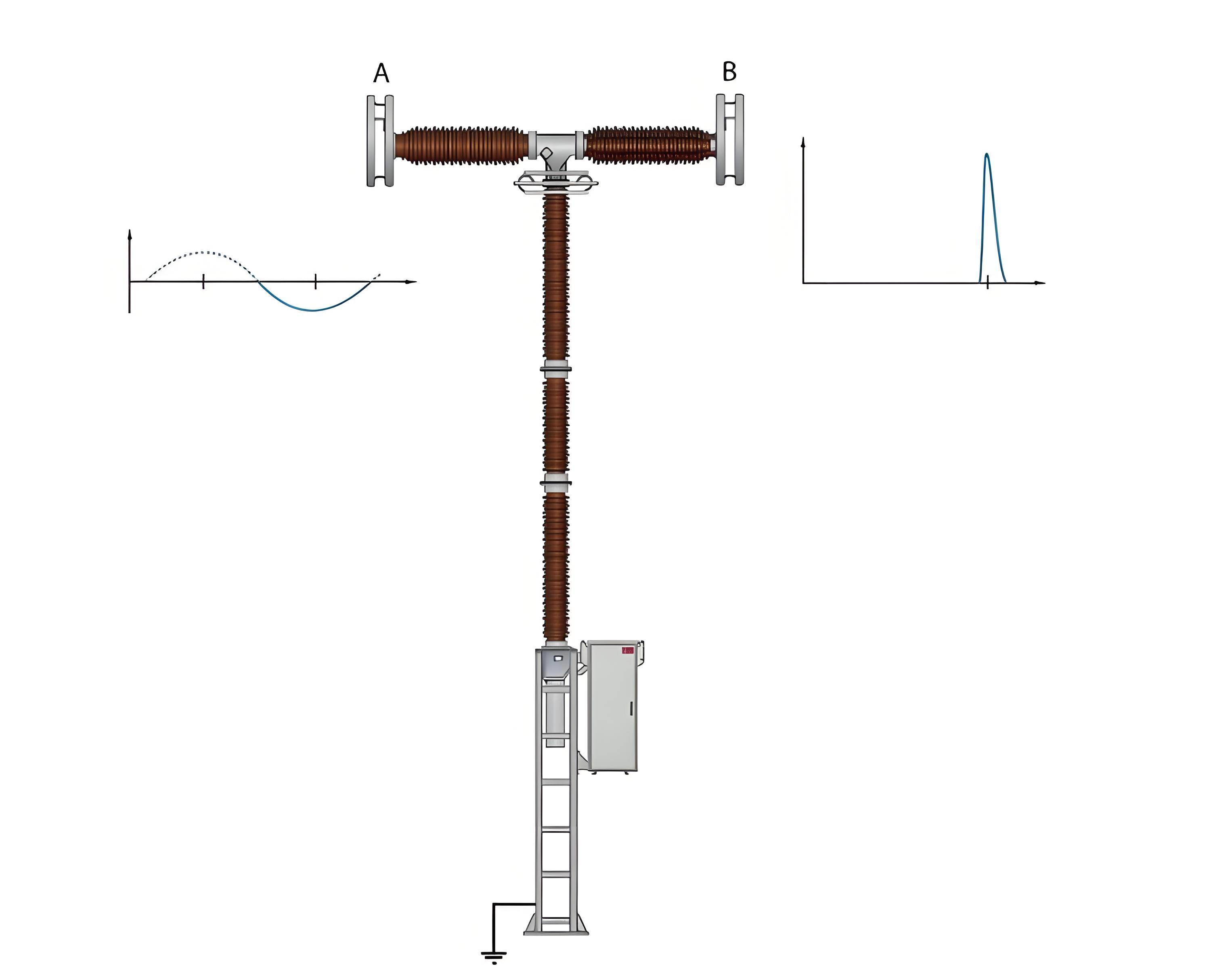
Example: ABB High-Voltage Circuit Breaker in Dielectric Bias Test
In the following scenario, an ABB high-voltage circuit breaker is being tested under dielectric bias conditions:
- Terminal A: Power frequency (PF) voltage is applied.
- Terminal B: Either a switching (SW) or lightning (LI) impulse is applied, synchronized with the maximum value of the negative PF voltage.
This setup ensures that the circuit breaker is tested under conditions that closely resemble those it would encounter in actual operation, providing a reliable assessment of its insulation performance.
Key Points Summary
- PF Voltage: Applied at one terminal, corresponding to the rated phase-to-ground voltage for SW bias tests or 70% of the rated voltage for LI bias tests.
- Impulse Voltage: Applied at the other terminal, synchronized with the opposite peak of the PF voltage.
- Total Voltage: The sum of the PF voltage and the impulse voltage.
- Synchronization: For SW bias tests, the impulse is synchronized with the maximum negative PF voltage; for LI bias tests, the same synchronization is used, but with a lower PF voltage.
- Purpose: To simulate real-world voltage conditions and ensure the circuit breaker's insulation can handle the combined stresses of power frequency and impulse voltages.