High voltage switchgear insulators creepage distance extending ways in substations

Edwiin
12/23/2024
Site Condition Severity Assessment and Insulator/Bushing Upgrade Strategy
Step-by-Step Approach:
-
Measure or Estimate Site Condition Severity:
- Environmental Factors: Assess the severity of environmental conditions such as pollution, humidity, temperature fluctuations, and salt spray (for coastal areas).
- Operational Data: Collect data on historical insulator performance, including flashover incidents, arcing, and contamination levels.
- Field Inspections: Conduct visual inspections to identify signs of degradation, such as tracking, erosion, and surface contamination.
-
Select Candidate Profile and Creepage Guidance:
- Creepage Distance Calculation: Based on the site condition severity, calculate the required creepage distance to ensure reliable insulation performance.
- Profile Selection: Choose an insulator profile that provides adequate leakage paths and resists water bridging. Alternating shed profiles are particularly effective in preventing continuous paths of conductive moisture.
-
Choose Applicable Laboratory Tests and Test Criteria:
- Pollution Withstand Tests: Perform laboratory tests to evaluate the insulator's ability to withstand pollution under simulated field conditions.
- Hydrophobicity Tests: Assess the hydrophobic properties of the insulator material, which can help reduce the risk of flashover in wet conditions.
- Mechanical Stress Tests: Ensure that the insulator can withstand mechanical stresses, especially if longer or heavier insulators are considered.
-
Verify/Adjust Candidates:
- Field Trials: Install a small number of candidate insulators in the field and monitor their performance over time.
- Adjustments: Based on the test results, make any necessary adjustments to the insulator design or material selection.
Two Options for Upgrading Insulators/Bushings:
-
Replacement of Existing Insulators with Higher Creepage Distance Units:
- Advantages:
- Provides a long-term solution by ensuring adequate creepage distance.
- Can improve overall system reliability and reduce maintenance costs.
- Disadvantages:
- Increased weight and higher initial costs due to longer leakage paths.
- May require structural modifications to support the heavier insulators.
- Installation downtime may be required.
- Advantages:
-
Installation of Additional Creepage Boosters/Extenders:
- Description:
- Creepage boosters/extenders are polymeric skirts coated internally with a specially formulated compound. When heated, the skirt shrinks around and bonds onto the existing insulator sheds, increasing the effective diameter and creepage distance.
- Advantages:
- Cost-effective solution compared to replacing entire insulators.
- Minimal installation downtime, as the boosters can be added to existing insulators.
- Flexibility to change the shed profile, improving resistance to water bridging.
- Disadvantages:
- May not provide the same long-term durability as new insulators with higher creepage distance.
- Requires careful installation to ensure proper bonding and performance.
- Description:
Water Bridging and Shed Profiles:
- Water Bridging: A continuous path of contaminated conductive moisture that can cause arcing and flashover. This is a common issue in polluted environments, especially when insulators have uniform shed profiles.
- Alternating Shed Profiles: By using insulators with alternating shed profiles, the risk of water bridging is significantly reduced. The irregular shape of the sheds disrupts the formation of continuous moisture paths, enhancing the insulator's performance in wet and contaminated conditions.
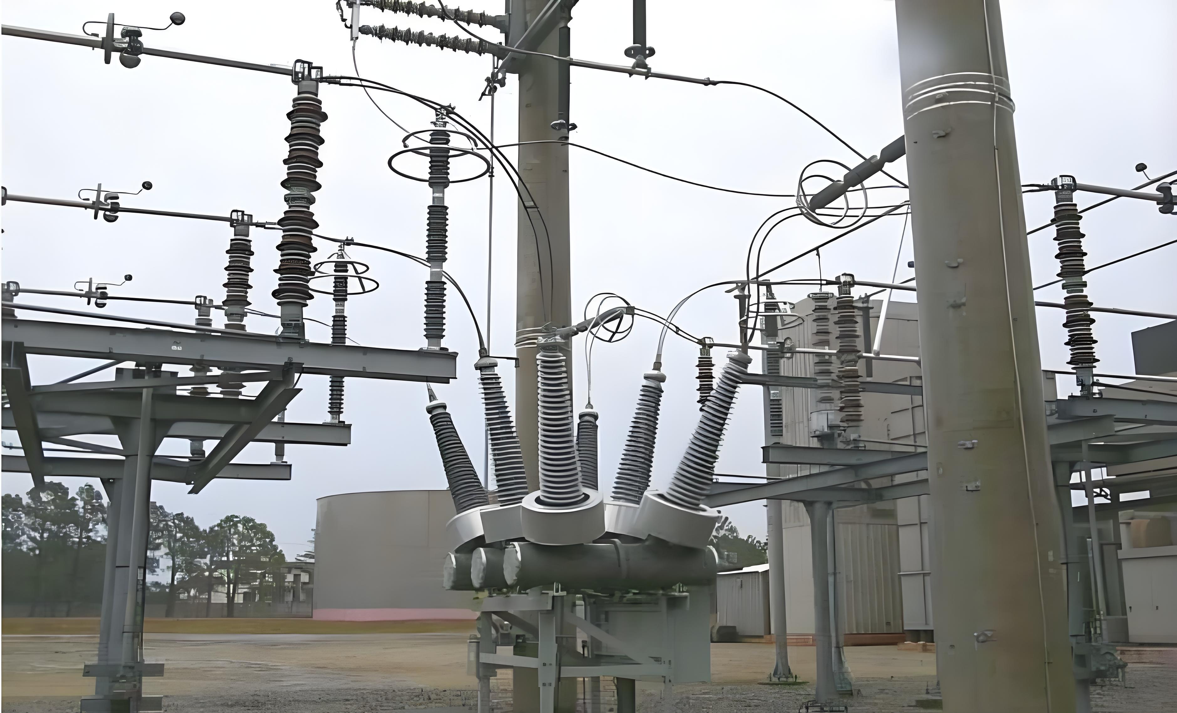
Visual Representation:
The provided image shows insulators with creepage boosters/extenders installed in a substation. These boosters increase the effective creepage distance and shed diameter, improving the insulator's ability to resist flashover and arcing in harsh environmental conditions.
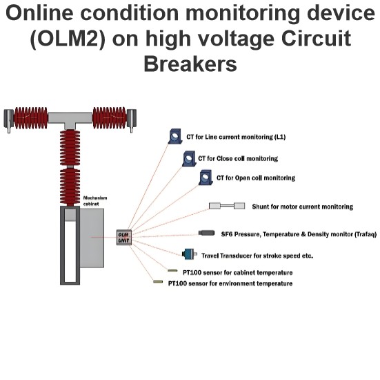
Online condition monitoring device (OLM2) on high voltage Circuit Breakers
This device is capable of monitoring and detecting various parameters according to the specifications outlined:SF6 Gas Monitoring:Utilizes a specialized sensor for measuring SF6 gas density.Capabilities include measuring gas temperature, monitoring SF6 leak rates, and calculating the optimal date for refilling.Mechanical Operation Analysis:Measures operational times for closing and opening cycles.Evaluates primary contacts separation speed, damping, and contact overtravel.Identifies signs of mec
Edwiin
02/13/2025
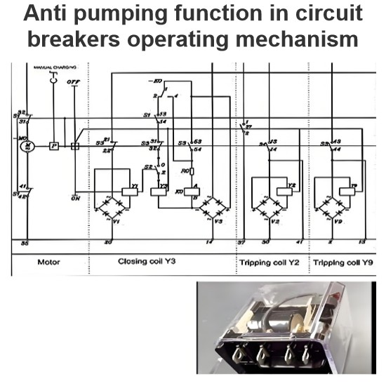
Anti pumping function in circuit breakers operating mechanism
The anti - pumping function stands as a crucial characteristic of control circuits. In the absence of this anti - pumping function, assume that a user connects a maintained contact within the closing circuit. When the circuit breaker is closed onto a fault current, the protective relays will promptly trigger a tripping action. However, the maintained contact in the closing circuit will attempt to close the breaker (once again) onto the fault. This repetitive and dangerous process is referred to
Edwiin
02/12/2025
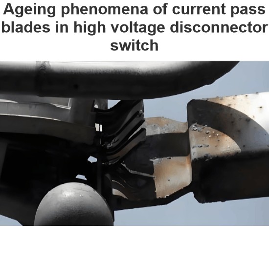
Ageing phenomena of current pass blades in high voltage disconnector switch
This failure mode has three primary origins:Electrical Causes: The switching of currents, such as loop currents, can lead to localized wear. At higher currents, an electric arc may burn at a specific spot, increasing the local resistance. As more switching operations occur, the contact surface wears down further, causing an increase in resistance.Mechanical Causes: Vibrations, often due to wind, are the main contributors to mechanical aging. These vibrations cause abrasion over time, leading to
Edwiin
02/11/2025
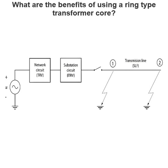
Initial Transient Recovery Voltage (ITRV) for high voltage circuit breakers
Transient Recovery Voltage (TRV) stress similar to that encountered during a short-line fault can also occur due to the busbar connections on the supply side of a circuit breaker. This specific TRV stress is known as Initial Transient Recovery Voltage (ITRV). Given the relatively short distances involved, the time to reach the first peak of ITRV is typically less than 1 microsecond. The surge impedance of the busbars within a substation is generally lower compared to that of overhead lines.The f
Edwiin
02/08/2025


