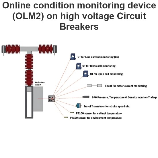
Short Line Fault interruption(SLF) principle in grid by circuit breakers

High-Frequency Transient Recovery Voltage (TRV) in Transmission Lines
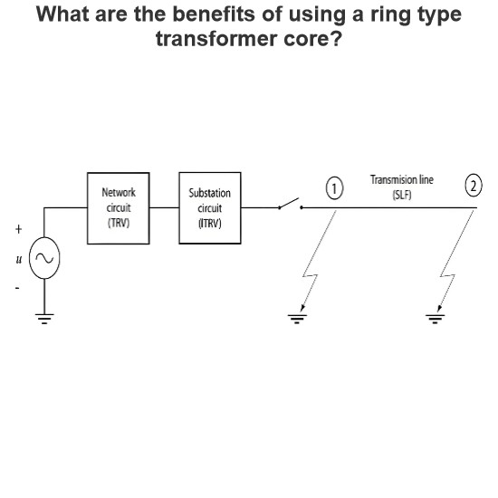
When a fault occurs on a transmission line at a distance ranging from 100 meters to several kilometers, a circuit breaker (CB) is required to clear the short-line fault (SLF). The process of clearing the fault by the circuit breaker can lead to the generation of a Transient Recovery Voltage (TRV) with a steep rate of rise, often resembling a sawtooth waveform. This phenomenon is caused by high-frequency oscillations generated by traveling waves that propagate along the line and reflect between the circuit breaker terminal and the fault point.
Key Phenomena During Fault Interruption
-
High-Frequency Oscillations and Sawtooth Waveform:
- When the circuit breaker interrupts the fault current under SLF conditions, high-frequency oscillations are generated due to the rapid changes in current and voltage. These oscillations result in a TRV with a steep rate of rise, which can be visualized as a sawtooth or triangular waveform.
- The sawtooth shape is caused by the traveling waves that propagate along the transmission line and reflect between the circuit breaker terminal and the fault location. Each reflection contributes to the oscillatory behavior of the TRV, leading to multiple peaks and valleys in the voltage waveform.
-
Oscillations on the Source Side:
- On the source side of the circuit breaker (the side connected to the power system), the voltage at the circuit breaker terminal returns to the system voltage level, which is typically the voltage at the transformer terminal. This transition causes an oscillation at the power frequency (e.g., 50 Hz or 60 Hz) in the source circuit.
- The power-frequency oscillation is due to the sudden change in the circuit configuration when the fault is cleared, causing a transient response in the system. This oscillation gradually decays over time as the system stabilizes.
-
Oscillations on the Line Side:
- On the line side of the circuit breaker (the side connected to the transmission line), the voltage at the circuit breaker terminal drops to near ground potential after the fault is interrupted. This drop creates another oscillation, but this time it is characterized by a sawtooth (triangular) shape due to the traveling and reflecting waves along the line.
- The line side circuit can be approximated as a distributed parameter circuit with small attenuation. The reflections between the circuit breaker terminal and the fault point cause the voltage to oscillate, creating the sawtooth waveform. The frequency of these oscillations is much higher than the power frequency and is influenced by the propagation speed of the waves and the distance between the circuit breaker and the fault.
Approximation of the Line Side Circuit
The line side circuit can be modeled as a small attenuated circuit with distributed parameters, such as resistance, inductance, and capacitance per unit length. This model helps to understand the behavior of the traveling waves and their reflections. The key characteristics of this model include:
- Propagation Delay: The time it takes for a wave to travel from the circuit breaker terminal to the fault point and back.
- Reflection Coefficient: The ratio of the reflected wave amplitude to the incident wave amplitude, which depends on the impedance mismatch between the line and the fault.
- Attenuation: The reduction in wave amplitude as it travels along the line, which is influenced by the line's resistance and conductance.
TRV Waveforms Across Circuit Breaker Terminals and Line Side
The TRV waveforms observed across the circuit breaker terminals and on the line side can be summarized as follows:
-
Source Side (Circuit Breaker Terminal):
- The voltage returns to the system voltage level, causing a power-frequency oscillation.
- The oscillation is relatively slow compared to the high-frequency oscillations on the line side.
-
Line Side (Circuit Breaker Terminal):
- The voltage drops to near ground potential, resulting in a high-frequency sawtooth (triangular) waveform.
- The sawtooth shape is due to the rapid changes in voltage caused by the traveling and reflecting waves along the line.
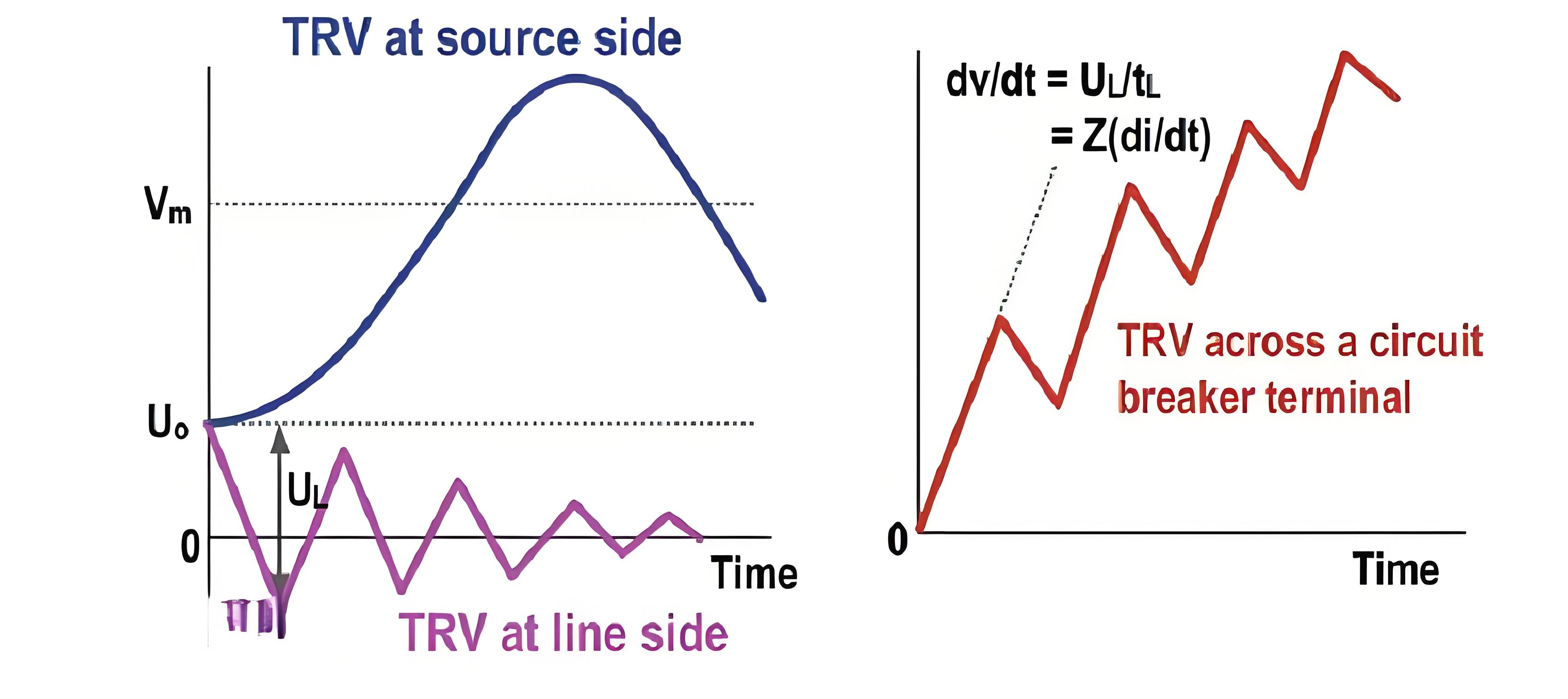
Visual Representation of TRV Waveforms
A typical figure showing the TRV waveforms across the circuit breaker terminals and on the line side would illustrate:
- Source Side TRV: A waveform with a gradual rise to the system voltage, followed by a power-frequency oscillation.
- Line Side TRV: A waveform with a sharp drop to near zero, followed by a series of high-frequency peaks and valleys, forming a sawtooth or triangular shape.