Voltage Escalation in Shunt Reactor Switching in Circuit Breakers
Shunt-Reactor Switching: A Common Practice in Inductive-Load Switching
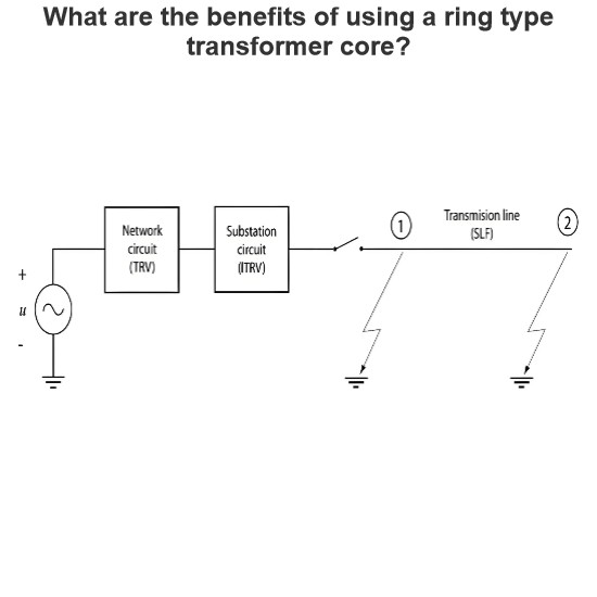
Shunt-reactor switching is one of the most common practices in inductive-load switching. Shunt reactors are installed to compensate for overhead-line capacitance and are switched in or out based on the momentary line load. Since a shunt reactor can be treated as a lumped circuit element with stray capacitance, the equivalent load circuit can be simplified to a straightforward LC (inductor-capacitor) circuit.
Voltage Oscillations at Interruption
At the moment of interruption, which often involves current chopping, the LC circuit produces voltage oscillations. The maximum voltage, , reaches a peak that is 1 per unit (p.u.) of the system voltage augmented by the additional contribution from the current chopping. Typically, the single-frequency oscillatory transient recovery voltage (TRV) is of high frequency, standardized by IEC 62271-110 to values between 6.8 kHz at a rated voltage of 72.5 kV and 1.5 kHz at 800 kV.
Short Arcing Time and Re-ignition Risk
Similar to capacitive-current switching, the reactor current is low enough that interruption can occur after a very short arcing time. This short duration implies that the circuit-breaker gap might not have reached a sufficient spacing at the current zero point to withstand the TRV. If this occurs, a breakdown happens, leading to a re-ignition. In this case, the re-ignition is termed a re-ignition because the high-frequency TRV causes it to occur within a quarter of a power-frequency period after the interruption.
Low Energy Discharge in Inductive Re-ignition
Unlike a restrike in capacitive circuits, the energy delivered to the inductive re-ignition discharge is relatively low, being primarily the discharge of the stray capacitance. A brief high-frequency re-ignition current will flow, and the gap may or may not recover from the event. During the flow of re-ignition current, the opening gap reaches only a slightly higher breakdown voltage. After the re-ignition current is interrupted, the subsequent higher TRV can again lead to re-ignition. This is more likely to occur because, during the brief conducting period, the power-frequency current in the reactor increases slightly, causing the second TRV to be steeper and potentially higher than the previous one.
Multiple Re-ignitions and Voltage Escalation
The sequence of re-ignitions is called multiple re-ignitions, and the gradual increase in the re-ignition voltage value is referred to as (inductive) voltage escalation. Multiple re-ignitions can be particularly challenging for gas and oil circuit breakers, which is why shunt-reactor switching is sometimes termed "a circuit-breaker's nightmare." This is especially true because shunt-reactor switching is a daily operation, making it a frequent source of stress for these devices.
Analysis of SF6 Circuit Breaker Test with Multiple Re-ignitions
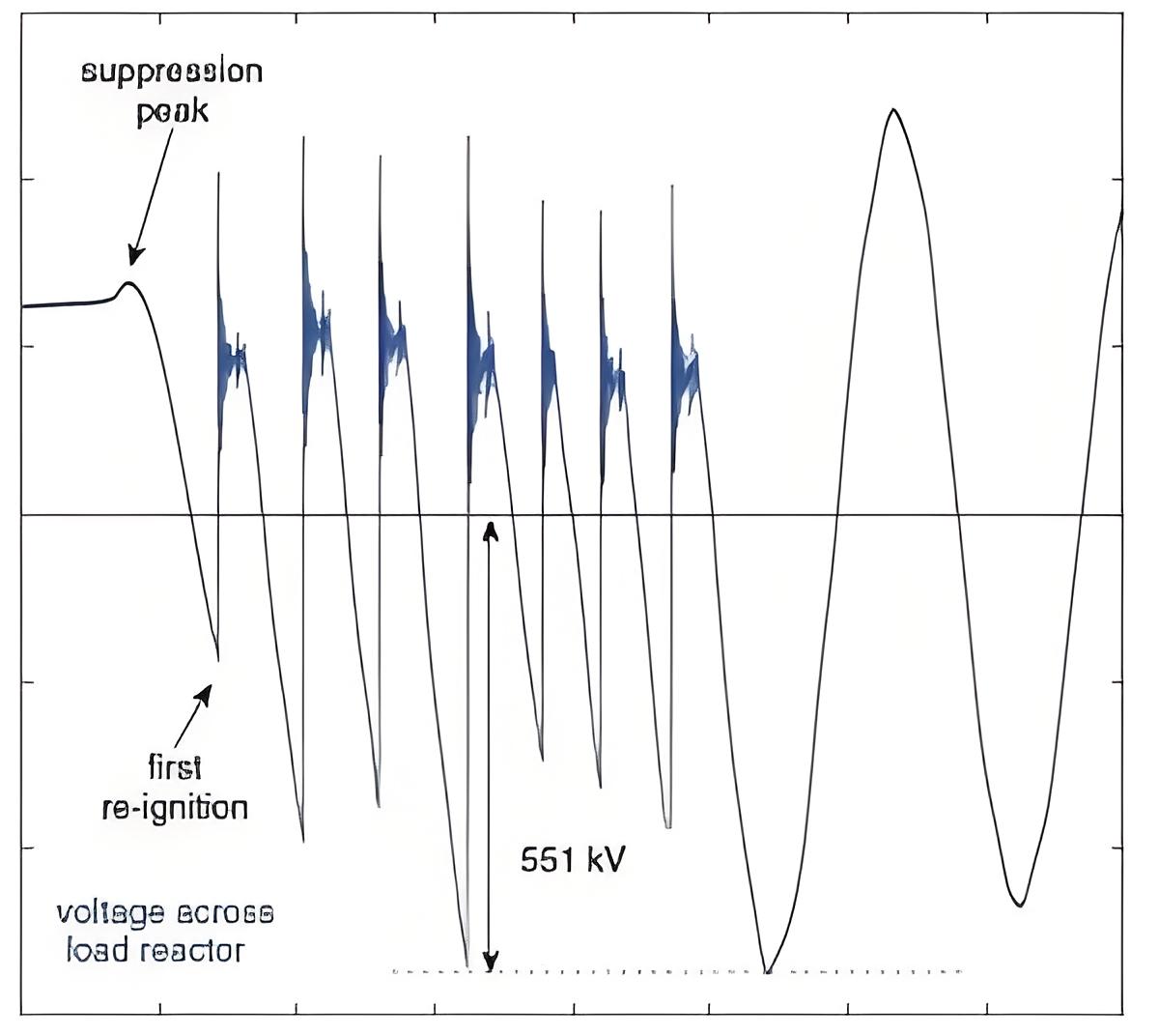
In the given figure for an SF6 circuit breaker test, seven re-ignitions can be observed before recovery is achieved. Immediately after each re-ignition, a re-ignition current of very high frequency keeps the gap conducting for approximately 100 μs. The maximum voltage reached across the load reactor is 2.3 p.u.. Without the re-ignitions, the maximum voltage would have been 1.08 p.u. due to the very small chopping current. The peak value of the transient recovery voltage (TRV) is 3.3 p.u..
Key Observations:
-
Multiple Re-ignitions: Despite the very small chopping current, the load voltage escalates significantly after multiple re-ignitions. This highlights the critical impact of re-ignitions on the system's voltage levels.
-
High-Frequency Re-ignition Current: The re-ignition current is characterized by its very high frequency, which keeps the gap conducting for a brief period (approximately 100 μs). This short duration of conduction allows the voltage to build up rapidly, leading to subsequent re-ignitions.
-
Voltage Escalation: The maximum voltage across the load reactor reaches 2.3 p.u., which is more than double the expected voltage without re-ignitions (1.08 p.u.). The peak TRV value of 3.3 p.u. further underscores the severity of the voltage escalation caused by multiple re-ignitions.
Preventing Multiple Re-ignitions in Shunt-Reactor Switching
Multiple re-ignitions during shunt-reactor switching can be effectively avoided through controlled switching techniques. Instead of relying on random contact separation, controlled switching ensures that the contacts separate well in advance of the current zero point. This approach offers several advantages:
-
Avoiding Short Arcing Times: By separating the contacts in advance, the arcing time is extended, allowing the gap to reach sufficient spacing before the current naturally reaches zero. This reduces the risk of re-ignition, as the gap is better prepared to withstand the transient recovery voltage (TRV).
-
Timely Interruption: Controlled switching ensures that the interruption occurs when the gap has already reached a sufficient spacing. This timing minimizes the likelihood of re-ignition and helps maintain stable system performance.
-
Reduced Voltage Escalation: By preventing re-ignitions, controlled switching also mitigates the risk of voltage escalation. The system voltage remains closer to the expected values, reducing stress on insulation and other components.
Benefits of Controlled Switching
-
Enhanced Reliability: Controlled switching improves the overall reliability of the circuit breaker, especially in applications involving shunt reactors. It reduces the occurrence of multiple re-ignitions, which can otherwise lead to equipment damage or system instability.
-
Improved Performance: By avoiding re-ignitions, controlled switching ensures that the circuit breaker operates within its design parameters, maintaining optimal performance and extending the lifespan of the equipment.
-
Cost Savings: Reducing the frequency of re-ignitions can lead to cost savings by minimizing maintenance requirements and preventing potential equipment failures.
