High voltage Incoming and outgoing feeders configuration in switch yards
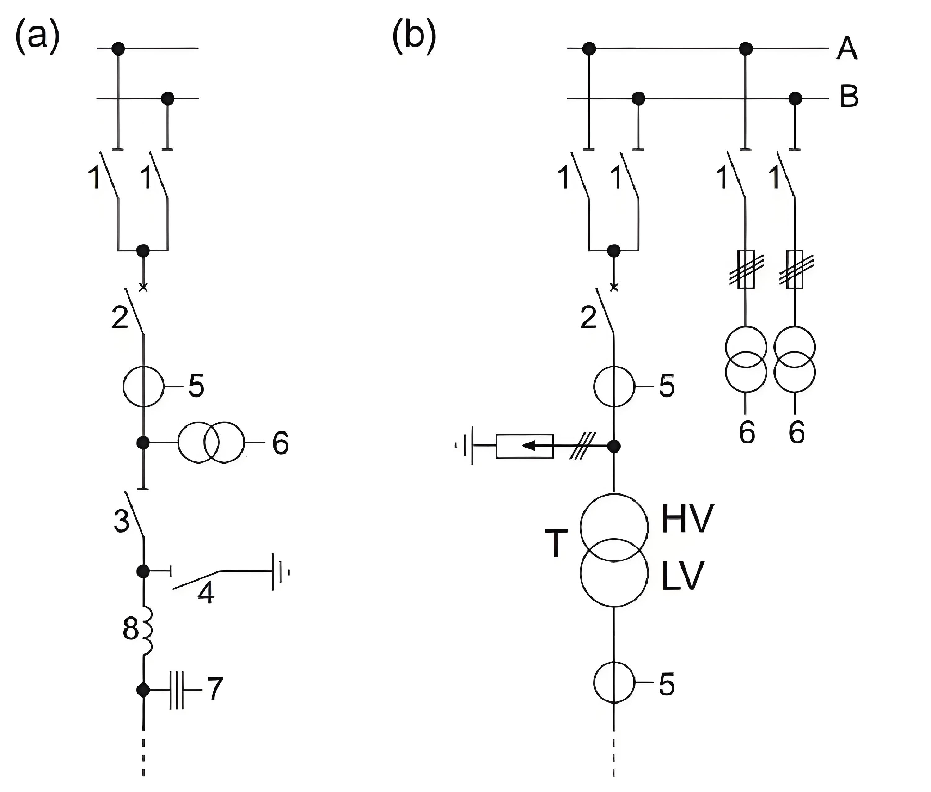
The incoming and outgoing feeders of switchgear cabinets are typically equipped with circuit breakers, isolating switches, and earthing switches to ensure the safe operation of the power system. In high-voltage switch stations, each feeder is also fitted with current transformers (CTs) and potential transformers (PTs) to connect protection and measurement devices. CTs are positioned on the busbar side of the PTs to allow protection devices to detect short circuits in the PTs. For feeders without their own PTs, the PTs are installed on the busbar to ensure busbar voltage monitoring is unaffected by individual feeder faults.
Additionally, depending on the specific requirements of the switchgear cabinet, feeders may be equipped with surge protection devices to prevent damage from lightning strikes or transient overvoltages. Coupling devices for frequency carrier signals may also be installed on the feeders to transmit communication signals or control commands, enabling remote monitoring and automated operations.
The diagram shows the typical configuration of various devices in a feeder arrangement, including current transformers, potential transformers, circuit breakers, isolating switches, earthing switches, surge protection devices, and coupling devices for carrier signals. This layout ensures the reliability and safety of the feeder while providing necessary support for protection and measurement.
(a) Overhead line feeder with double busbar.
(b) transformer feeder with double busbar.
- Busbar disconnecting switch
2) Circuit breaker
3) Feeder disconnecting switch
4) Earthing switch
5) Current transformer
6) Voltage transformer
7) Capacitive voltage transformer with coupling for frequency carrier signal
8) Blocking reactor against frequency carrier signals
