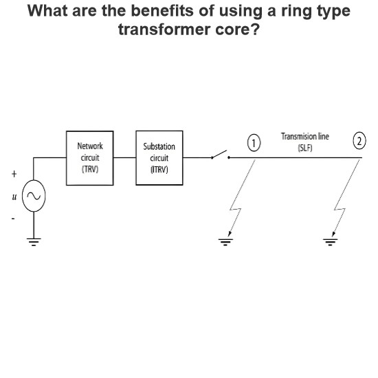
Description of the basic phenomena during circuit breaker switching in grids
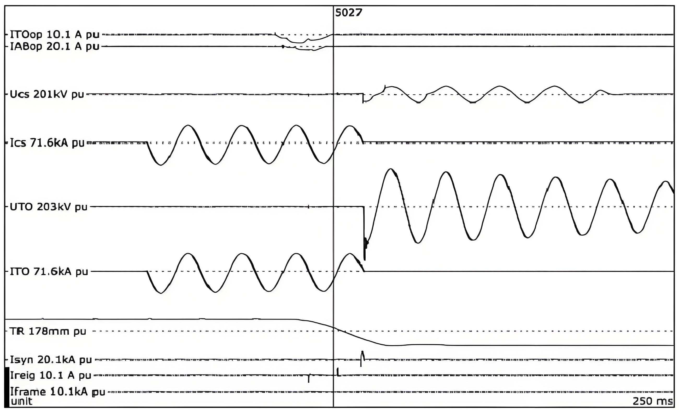
Circuit breaker switching terminology can be understood by considering an actual event.
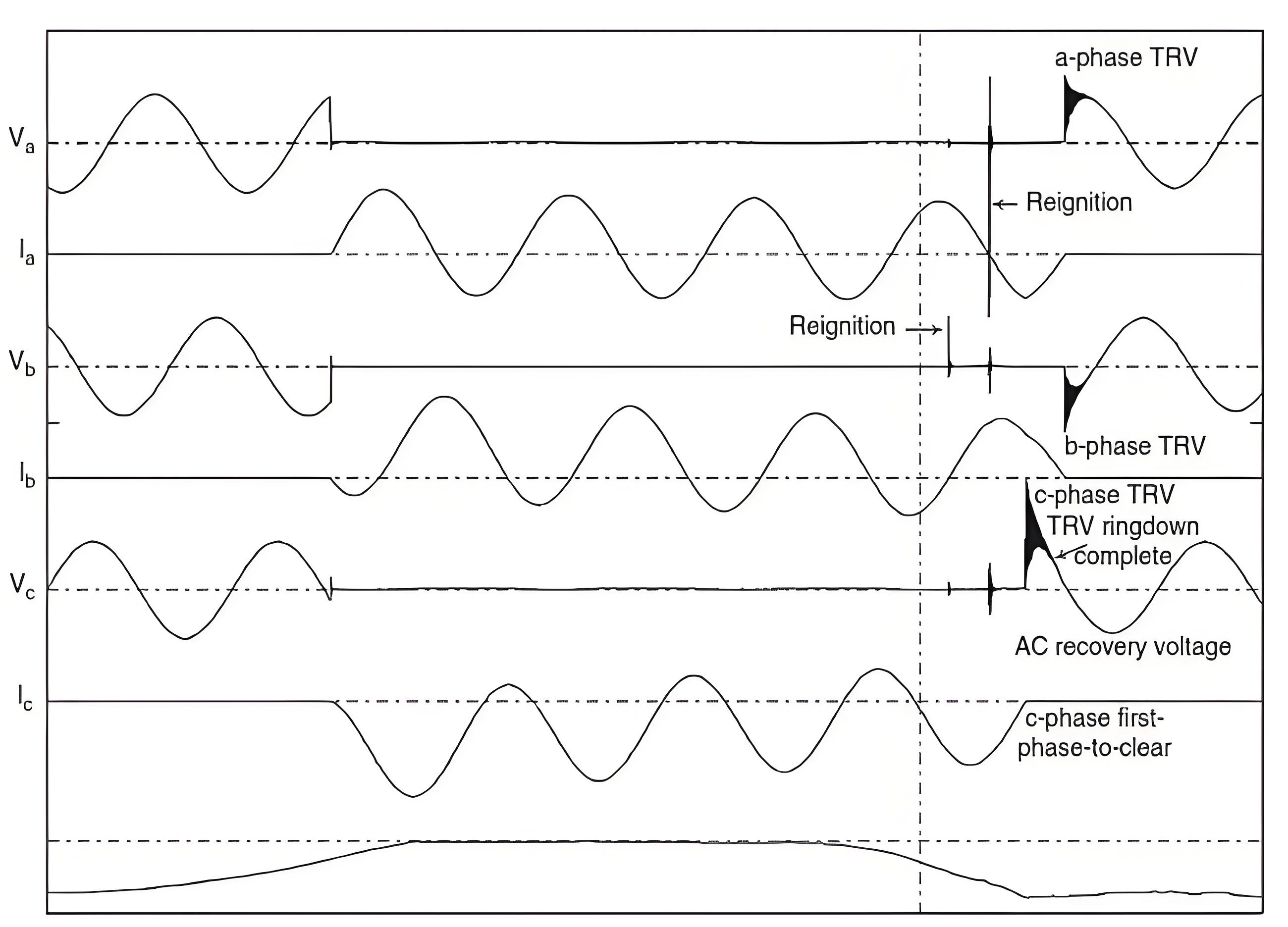
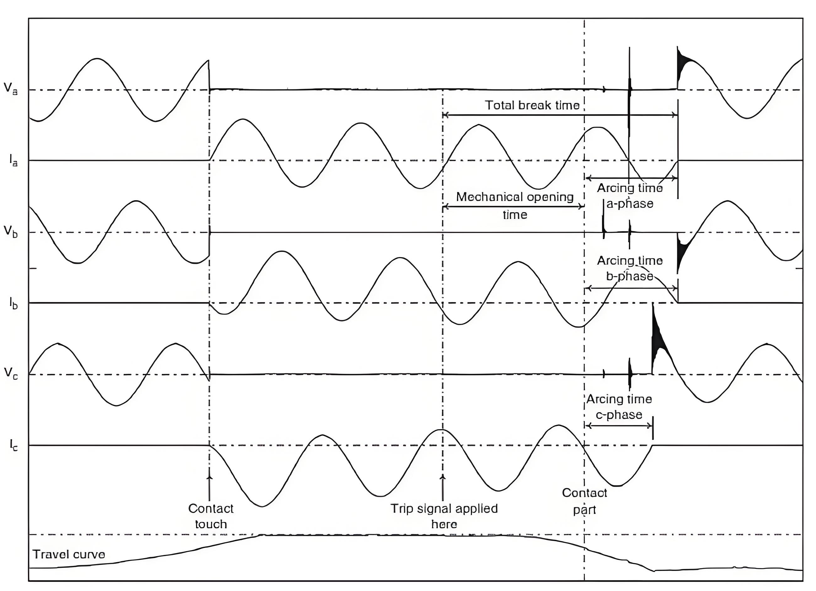
Figures 1 to 3 show the trace of a close-open (CO) three-phase unearthed fault current test on a vacuum circuit breaker (trace courtesy of KEMA).
Taking each figure in turn, the terminology is as follows:
Circuit Breaker Tripping Sequence and Related Quantities
From Figure 1, we can observe the following sequence of events in detail:
1.Initial State:
- The circuit breaker starts in the open position.
- A closing signal is applied to the closing coil to initiate the closing operation.
2.Closing Process:
After a brief electrical delay, the moving contact begins to move (as indicated by the bottom curve of the travel graph) and eventually makes contact with the stationary contacts. This moment is referred to as contact engagement or contact closure. In practice, due to pre-breakdown between the contacts, the actual electrical connection may occur slightly before the mechanical contact.
The time interval between the application of the closing signal and the moment of contact engagement is known as the mechanical closing time.
3.Closed State and Fault Current:
- Once closed, the circuit breaker carries the fault current. A tripping signal is then applied to the tripping coil, initiating the opening (or tripping) process of the circuit breaker.
- After a brief electrical delay, the moving contact begins to move away from the stationary contacts, resulting in their mechanical separation. This moment is referred to as contact parting, contact separation, or contact opening.
- The time interval between the application of the tripping signal and the moment of contact parting is known as the mechanical opening time.
4.Arc Formation and Current Interruption:
- An electric arc forms between the contacts as they separate. The current attempts to interrupt at the zero-crossing points, first in phase b, followed by phase a, and finally successfully in phase c.
- Phase c is the first phase to achieve complete interruption, with an arc duration (the time between contact parting and current interruption) of approximately half a cycle. The interrupting time (also called the breaker time) for phase c is the sum of the mechanical opening time and the arc duration.
5.Current Distribution During Interruption:
- At the moment of current interruption in phase c, the currents in phases a and b shift by 30°, becoming equal in magnitude but opposite in polarity. The current in the leading phase (phase a) experiences a shortened half-cycle, while the current in the lagging phase (phase b) experiences an extended half-cycle.
- The total clearing time is the sum of the mechanical opening time and the maximum arc duration observed in either phase a or phase b.
Circuit breaker switching current-related quantities:
It can be seen carefully in figure 2 that:
- For a fault initiated at a voltage peak, the current will be symmetrical. Symmetrical means that each half-cycle of the current also referred to as a loop of current, will be identical to the preceding half-cycle of current. The current in a-phase is near symmetrical as a result of fault initiation just prior to the voltage peak.
- The currents in the b-phase and c-phase are asymmetrical and consist of long and short loops of current referred to as major loops and minor loops, respectively.
Maximum asymmetry occurs when the fault is initiated at a voltage zero crossing.
Circuit Breaker Switching Voltage-Related Quantities
From Figure 3, we can observe the following sequence of events in detail:
Current Zero Crossings:
A current zero crossing occurs every 60 seconds. After the contacts part, the pole closest to the next zero crossing will attempt to interrupt the current first. In this case, the b-phase pole, being the closest to the first zero crossing, attempts to interrupt the current.
2. Initial Current Interruption Attempts:
The b-phase pole attempts to interrupt the current but fails due to the contacts being too close to withstand the Transient Recovery Voltage (TRV), leading to re-ignition.
Subsequently, the a-phase pole also attempts to interrupt the current but similarly fails and re-ignites.
3. Successful Current Interruption:
Finally, the c-phase pole successfully interrupts the current, restoring the system to the TRV and the alternating recovery voltage (AC recovery voltage).
4. Transient Recovery Voltage (TRV):
- Definition: TRV is the transient oscillation that occurs as the voltage on the power side of the circuit breaker recovers to the pre-fault system voltage.
- Behavior: TRV oscillates around the AC recovery voltage, which serves as the target point or axis of oscillation. The peak value of TRV depends on the damping in the circuit.
- Oscillation Duration: As shown in the waveform, TRV oscillates over one-quarter of a power frequency cycle (i.e., 90 degrees).
- Impact on Poles: The first pole to clear (in this case, the c-phase) is exposed to the highest TRV, as it experiences the full transient oscillation.
5. Subsequent Pole Clearing:
- The a-phase and b-phase poles clear 90 degrees later than the c-phase.
- For these poles, the TRV values are lower than those experienced by the c-phase and have opposite polarities.
- The AC recovery voltage is the line voltage, shared between the two phases.
