Important points for SF6 gas leakage on-site test for high voltage switchgear
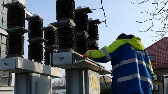
SF6 Gas Leakage Testing on Site
Purpose
SF6 gas leakage testing is conducted to ensure that there are no gas leaks at the field-assembled joints of Gas-Insulated Switchgear (GIS). Leaks can occur during field assembly due to various factors such as damaged sealing surfaces, improper placement, incorrect application of seals, seal damage or omission, improper application of lubricants and sealants, misalignment or inadequate tightening of mating surfaces, and contamination.
Scope
- Exclusions: There is no need to check for leaks in the chamber walls or factory-assembled joints, as these have already been tested for leaks in the factory.
- Exceptions: The only exceptions are if suspected damage occurred during transportation, assembly, or on-site maintenance. If any factory joints are disassembled for any reason during field assembly, they must be retested.
Procedure
- Filling the GIS with SF6 Gas
- After the GIS is assembled, fill it with SF6 gas or the required gas mixture to the manufacturer's recommended temperature-corrected pressure, as indicated on the nameplate.
- Use a portable gas leak detector to verify the absence of gas leaks. A detector that provides leak levels and leak rates is recommended, but a standard handheld "pass/fail" (audible) leak detector can be used for initial verification.
- Vacuum Rise Test
- Purpose: Conduct a vacuum rise test before filling the GIS with SF6 gas to identify large leaks in the field-assembled flanges/joints. This test may not detect leaks once the container is pressurized.
- Procedure:
- Measure the vacuum loss in the chamber after disconnecting the vacuum pump but before charging the gas (using a vacuum gauge).
- Manufacturers will provide acceptable vacuum loss values over a predetermined period.
- If significant vacuum loss is observed, suspect a leak.
- Caution: Factors like leaks from the vacuum gauge and vacuum handling equipment, as well as vacuum loss due to moisture inside the chamber (which may outgas from internal epoxy materials), can cause false readings. Consult with the manufacturer regarding the vacuum process and follow their recommendations before filling the equipment.
- SF6 Gas Leak Detection
- Timing: Perform SF6 gas leak testing immediately after filling the GIS to the manufacturer's recommended temperature-compensated pressure.
- Testing Areas: Test all field-assembled enclosure joints, field welds, field-connected monitoring equipment, gas valves, and gas piping.
- Accumulation Testing: For intermittent leaks, consider using an accumulation test. In this method, the area to be tested is enclosed for a period, and then the leak detector is inserted into the enclosed space to measure any accumulated SF6 gas. This helps in detecting intermittent leaks that might be missed by quickly moving the detector over the area.
- Bagging Method
- Purpose: To capture intermittent SF6 gas molecules and avoid background interference.
- Procedure:
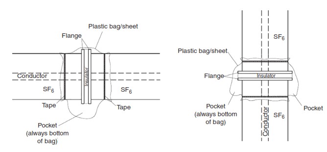
- Wrap the area to be tested with plastic sheeting to form a "bag" (see Figure 1 for best practices).
- Ensure that the bag is sealed tightly to prevent external air from entering.
- Place a cap or cover on self-sealing filling valves to avoid measuring residual gas along with the test sample.
- Testing: After 12 hours, perform a leak test on each bagged joint. Make a small incision above the pocket without disturbing the bag (as shown in Figure 1).
- Additional Verification
- If a leak is suspected, conduct additional on-site leak tests and verify factory-assembled joints as well.
Using a Handheld SF6 Gas Detector for Leak Detection
Procedure for Inserting the Detector Nozzle
- Insertion into the Bag:
- Carefully insert the nozzle of the handheld SF6 gas detector through the small incision made in the plastic bag, ensuring it reaches the bottom pocket of the enclosed area.
- This method helps to capture any accumulated SF6 gas that may have leaked into the bag.
- Consult Manufacturer Guidelines:
- Operators should consult the manufacturer's guidelines to understand the acceptable leakage rate standards for the specific testing equipment being used.
- Record the leakage rate (in ppmv) or pass/fail results for all tested positions on the GIS.
- Verification of Leaks:
- If a leak is detected, move the detector away from the suspected leak area, recalibrate it, and then return to the area to verify the presence of the leak.
- This step ensures accurate readings and minimizes false positives.
- Additional Investigation:
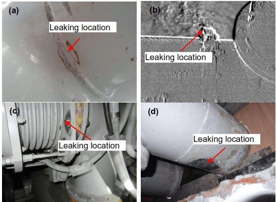
- If a leak is confirmed using the handheld leakage detector, further investigation is necessary to pinpoint the exact location of the leak.
Options for Identifying the Leak Location
- Liquid Leak Detection Solution or Soap Water:
- Procedure: Remove the plastic bag and apply a liquid leak detection solution or soapy water around the suspected leak area.
- Note: This method is less sensitive than using a gas leak detector and may not precisely identify the exact location of the leak. However, it can help confirm the general area where the leak is occurring.
- Handheld Leakage Detector Re-Check:
- Procedure: Remove the plastic bag and use the handheld leakage detector to check around the suspected leak joint.
- Rate of Movement: The rate at which the detector is moved around the area should be determined by the manufacturer’s recommendations to ensure thorough and accurate testing.
- Infrared Camera:
- Procedure: After the bag test, use an infrared camera to locate small leaks. This method is particularly useful for identifying leaks that are difficult to detect with other methods.
- Advantage: Infrared cameras can provide visual confirmation of the leak location without the need for physical contact.
- Isolation with Segmented Bags:
- Procedure: Repeat the leakage test using segmented bags to isolate the suspected leak area. This approach reduces the labor required for disassembly, correction, and reassembly.
- Benefit: It allows for more precise localization of the leak, minimizing unnecessary work.
Leak Repair Procedure
- Confirm and Document the Leak:
- Once the leak is confirmed, document the location and extent of the leak.
- Prepare for Repair:
- Recovery of SF6: Recover the SF6 gas from the affected chamber to prevent environmental contamination.
- Disassembly: Carefully disassemble the GIS to access the leak site.
- Identify the Cause: Determine the root cause of the leak, such as damaged seals, improper assembly, or contamination.
- Cleaning and Replacement: Clean the affected area and replace any damaged components or seals. In some cases, the customer and manufacturer may agree to use permanent sealing devices, clamps, or patches to address the issue.
- Reassembly and Testing:
- After repairs are completed, reassemble the GIS.
- Vacuum and Refill: Draw a vacuum on the chamber and refill it with SF6 gas to the manufacturer’s recommended temperature-compensated pressure.
- Final Leak Test: Conduct a final leak test to ensure that the repair was successful and no new leaks have developed.
The leak detection process will then be repeated.
It is likely the installation schedule will be affected if a leak is found on the equipment.
Certain chemicals used in sealing/assembling the GIS such as alcohol And silicone sealant may have an effect on the equipment used To detect a leak causing a false reading.
Dust,cobwebs,water,and other contaminants are also known to cause a false reading.
Prior to leak testing, always ensure the area to be tested is clean and dry.
If a condition-based monitoring/gas trending system is included with the new GIS,it is important to recognize that the sensors take some time to normalize, and therefore may not be effective In providing a true indication of gas leaks immediately after filling the equipment.
