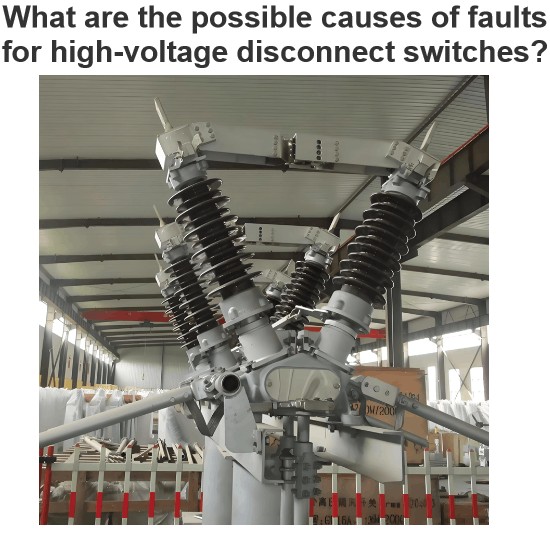
In summary, the primary causes of high-voltage disconnect switch (HVD) opening/closing failures can be categorized into two types: electrical control circuit faults and mechanical system faults. This paper focuses on the electrical control circuit, which mainly includes motor circuit failures, limit switch malfunctions, and secondary circuit issues. Analysis shows that high switching failure rates are predominantly attributed to motor and secondary circuit faults, significantly impacting HVD operation. Thus, resolving the safety and reliability of HVD operating mechanisms is urgent.
1. Research Status of High-Voltage Disconnect Switches
Relevant researchers and engineers have conducted extensive studies on the above issues and proposed constructive solutions, summarized in two key aspects:
1.1 Research Status of Secondary Circuit Faults
Numerous studies have addressed electrical component issues in secondary circuits. Poor sealing of the operating mechanism box allows rainwater ingress, causing component corrosion, auxiliary switch/relay failure, loose button contacts, and mechanical jams—leading to switching refusal or incomplete operation. Proposed solutions include regular maintenance, moisture protection, and fault flowcharts for rapid troubleshooting.
For mechanical wear such as deformed pins, loose limit bolts, or worn screws due to motor inertia, measures like frequent inspections and timely defect elimination are recommended. Anti-oxidation materials are suggested for corroded wire joints, while voltage/resistance testing methods help diagnose secondary circuit faults—enhanced by defect logging to improve troubleshooting efficiency. Heating devices have been proposed to address humidity-induced issues like auxiliary switch misalignment and poor contact in electric operating mechanisms.
However, existing studies merely list fault points and emphasize maintenance without fundamental solutions, reflecting low attention to secondary circuits. Maintenance personnel often undervalue electrical components relative to mechanical parts, and unfamiliarity with secondary component structures/principles—combined with neglected regular inspections—are indirect failure causes.
1.2 Research Status of Switching Accuracy Issues
To address switching accuracy and mechanical inertia, scholars have improved motor control by designing brushless DC motor (BLDC) and permanent magnet synchronous motor (PMSM) operating mechanisms. A BLDC-based HVD mechanism with a DSP core and dual closed-loop control strategy has shown effective switching speed regulation. Similar methods for real-time speed monitoring ensure smooth operation and improved closing accuracy, laying a foundation for smart grid development. Notably, these designs remain in theoretical research and laboratory simulation stages, with unproven reliability in practical applications.
2 Distributed Electric Operating Mechanism Design Scheme
Based on the above analysis, the primary cause of operating mechanism failures is the poor reliability of the electrical control circuit, which is highly susceptible to environmental factors. Delayed maintenance or other issues can damage electrical components, leading to switching failures. In response, this paper proposes a distributed design for electric operating mechanisms.
2.1 Distributed Control Concept for Electric Operating Mechanisms
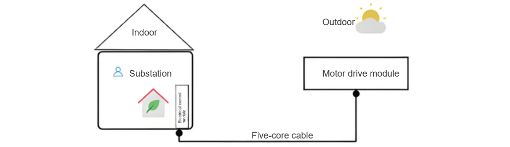
Distributed control divides the entire system into separate segments, each independently controlled by a main controller. This design separates the electrical control module from the motor drive module:
- The electrical control module, composed of electronic components with numerous wiring contacts, is vulnerable to environmental influences. It is thus placed in a substation with stable room temperature.
- The motor drive module, more resilient to environmental changes, is positioned near the high-voltage disconnect switch.
Considering the variable outdoor environment and cable susceptibility, a time-division shared cable strategy is adopted based on TRIZ's principle of multi-usage. Since motor control circuits and switching status indicator circuits do not need simultaneous activation, this approach enables signal transmission for both motor control and disconnect switch position indication using only 5 cables. This significantly reduces external environmental impacts on the electric operating mechanism. The overall control concept of the distributed electric operating mechanism is illustrated in Figure 2.
2.2 Design of Distributed Control Modules
The widely applied CJx-series electric operating mechanisms are designed with integrated electrical and mechanical components, operating outdoors year-round in a fixed configuration since commissioning. This integration is a key factor contributing to their high failure rate. The modular design disrupts this all-in-one outdoor setup by dividing the mechanism into two separate modules: an electrical control module and a mechanical drive module.
The modular design offers distinct advantages: it allows the electrical control module to be housed in a temperature-stabilized environment, significantly reducing environmental impacts on HVD switching operations; and it minimizes inter-module wiring, enabling quick replacement of faulty modules—prioritizing "replace-first, repair-later" to enhance maintenance efficiency and reduce grid downtime.
2.2.1 Electrical Control Module
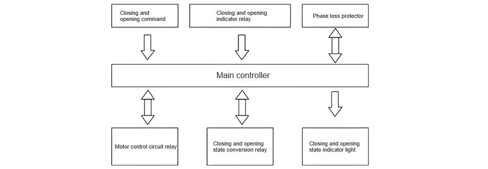
The electrical control module comprises a main controller, open/close transfer switch, relays, position indication circuits, and a phase-loss protector, as outlined in the design concept of Figure 3.
The control logic functions as follows: a switching signal (open/close) from the button is sent to the controller, which regulates motor operation based on the command. When the HVD is in the open state, the open-position circuit activates, lighting the indicator. Pressing the close button triggers the controller to engage the main motor relay and close-circuit transfer relay, driving the HVD to close. Upon completion, the motor relay de-energizes, activating the close-position circuit and indicator. The phase-loss protector safeguards the motor circuit with timer functionality, disconnecting the main circuit within a specified time frame in the event of faults.
2.2.2 Motor Drive Module
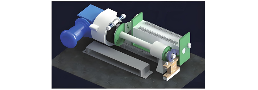
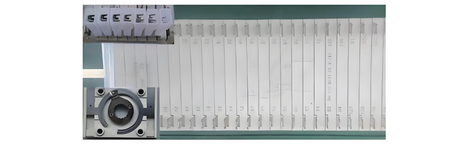
The motor drive module primarily consists of an AC motor, speed reducer, friction coupling, Siemens auxiliary switch, thyristor arc-suppression circuit, limit stops, and mechanical locking device. When the main controller sends an open/close command, the motor control circuit is activated, driving the speed reducer and main shaft via the motor for switching operations. Limit stops at the top of the main shaft, in conjunction with the mechanical locking device, control the switching position accuracy. Meanwhile, the Siemens auxiliary switch works with the thyristor arc-suppression circuit to disconnect the motor control circuit, halting motor operation. A 90-degree rotational margin at the connection between the speed reducer and main shaft enables no-load starting of the motor. The appearance of the motor drive module is shown in Figure 4.
2.3 Solution for Disconnect Switch Closing Accuracy
The closing action is a crucial step for high-voltage switchgear. Inadequate closing accuracy can affect the stable operation of the entire power system. To further enhance the opening and closing accuracy of the electric operating mechanism, this design employs a mechanical locking device, in conjunction with a Siemens auxiliary switch and a friction coupler, to improve the accuracy to a certain extent.
2.3.1 Siemens Auxiliary Switch and Thyristor Arc - Suppression Circuit
The auxiliary switch is connected to the main motor circuit to control the on - off of the motor circuit. The auxiliary switch is not prone to rust due to external environmental influences, and its internal friction mechanism prevents accidental closures. The contacts use a spring - loaded pin and a hard sheath to ensure stable and reliable connections. The specific structure is shown in Figure 6.
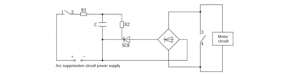
Design Principle of Thyristor Arc - Suppression Circuit: During the disconnection of the auxiliary switch, an arc is generated. To prevent the arc from being too large and damaging the switch, a thyristor arc - suppression circuit is connected in parallel with the auxiliary switch to absorb the arc. The specific circuit design is shown in Figure 7, where contacts 1, 2, 3, and 4 are all auxiliary switch contacts. (Contacts 1 and 2 are used to control the on - off of the thyristor arc - suppression circuit, and contacts 3 and 4 are used to control the on - off of the main motor circuit. It is set that contacts 1 and 2 disconnect after contacts 3 and 4 to achieve the purpose of arc suppression).
2.3.2 Function of the Friction Coupler
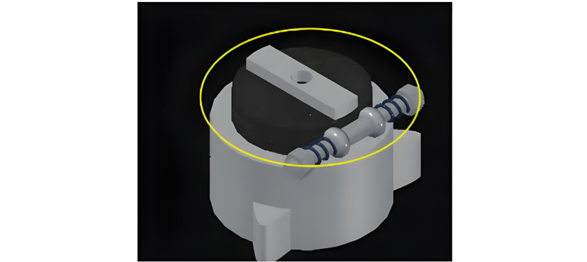
The friction coupler safeguards the motor under any abnormal operating conditions. Once the high - voltage disconnect switch is in place after closing, the main motor circuit is rapidly disconnected. However, due to mechanical rotational inertia, the motor cannot stop immediately. At this moment, the friction coupler acts as a force - relieving component. It enables the friction gear to idle, dissipating the motor's mechanical inertia and ensuring the precise positioning of the high - voltage disconnect switch during opening and closing operations. Additionally, by adjusting the tightness of the spring, the friction torque can be modified to suit the opening and closing operations of various disconnect switches. The friction coupler is shown in Figure 8.
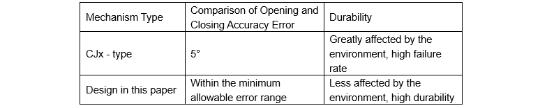
Advantages of the Designed Scheme over CJx - type Electric Operating Mechanisms
The proposed design eliminates electrical components like travel switches and limit switches, reducing instability factors and enhancing the reliability of the electric operating mechanism. It also removes the terminal block with numerous contacts, simplifying the wiring circuit. With a modular design, only five cables connect the two modules, greatly improving fault - repair efficiency. Additionally, it can form multiple protection layers with thermomagnetic circuit breakers and existing electronic motor protection devices. Even if the electrical control circuit malfunctions, the mechanical locking device and friction coupler ensure motor safety. The friction coupler counteracts the force from motor mechanical inertia, and the mechanical locking device prevents the limit stop from "rebounding", ensuring accurate opening and closing of the high - voltage disconnect switch and protecting its integrity. Moreover, the motor's no - load starting minimizes the starting current, avoiding equipment shock and extending the operating mechanism's service life.
3 Experimental Verification
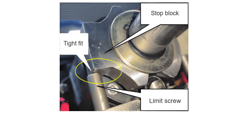
Adhering to relevant standards such as "High - Voltage AC Disconnect Switches and Earthing Switches" and "Common Technical Requirements for High - Voltage AC Switchgear and Controlgear", the combination of a mechanical locking device and a friction coupler further improves the opening and closing accuracy of the disconnect switch. Compared with the CJx series electric operating mechanisms, it offers higher reliability and safety. Error detection, through multiple opening and closing tests and angular deviation measurements between the limit stop and limit screw, shows that they are closely aligned, with an actual machining error within 1°, fully meeting the technological standards. The actual position is shown in Figure 9.