Thermal and Mechanical Performance Testing of Distribution Transformers: Ensuring Reliability and Longevity
Introduction
In the complex landscape of power distribution, distribution transformers play a pivotal role. These transformers are tasked with stepping down voltage from the primary distribution levels to the appropriate utilization voltages for end-users. Their proper functioning is crucial for maintaining a stable and efficient power grid. This article delves into two essential aspects of distribution transformer assessment: thermal performance testing and mechanical performance testing, while also exploring how to prevent service interruptions and manage voltage variations.
Thermal Performance Testing of Distribution Transformers
The Significance of Thermal Inspection
Distribution transformers generate heat during operation. Heat is primarily produced due to winding losses and core hysteresis within these transformers. Uncontrolled heat accumulation in transformers can lead to the degradation of insulation, accelerate the aging process of the transformers, and pose a significant risk of catastrophic failures. Regular thermal inspections of transformers are thus of utmost importance. These inspections, which include temperature monitoring and hotspot detection in transformers, act as early warning systems. By identifying thermal anomalies in transformers promptly, technicians can preempt breakdowns and ensure uninterrupted power delivery through the distribution network.
Key Thermal Testing Components for Transformers
Several tests form the basis of thermal performance inspections for distribution transformers:
Temperature Rise Test: A fundamental inspection for transformers, this test measures the temperature increase in the windings and oil of transformers under rated load. Deviations from the established standards in transformers signal potential issues such as inefficient cooling or internal resistance problems. Such findings prompt a closer inspection of components like cooling fans, fins, or coolant levels in transformers.
Thermal Imaging Inspection: Infrared cameras are employed in this non-invasive inspection technique for transformers. They map the surface temperatures of transformers, spotlighting hidden hotspots, which could be due to loose connections or blocked ducts within the transformers. This allows for targeted repairs in transformers before insulation damage occurs.
Oil Temperature Analysis: Sampling and testing the transformer oil’s viscosity and acid content provides insights into the thermal stress levels experienced by the transformers. Elevated acidity in the oil of transformers indicates excessive heating, triggering an inspection of the heat sources and cooling mechanisms within the transformers.
Inspection Protocols and Standards for Transformers
Standards such as IEEE C57.12.90 and IEC 60076 mandate systematic thermal inspections of transformers. During testing, technicians simulate full-load conditions on the transformers while closely monitoring temperature gradients. For instance, a temperature rise inspection in transformers requires stabilizing the transformers for several hours before recording readings. Detailed documentation of each inspection of transformers, including ambient conditions, test durations, and thermal profiles, facilitates trend analysis of the transformers over time.
Frequency and Adaptive Strategies for Transformer Inspections
The frequency of thermal inspections for transformers depends on various factors such as load variability and environmental conditions. Distribution transformers in urban areas with fluctuating loads may require monthly inspections, while those in rural areas might suffice with quarterly checks. In hot climates, the intervals between thermal inspections of transformers are shortened to counter the effects of heat stress. Advanced monitoring systems now enable continuous thermal inspections of transformers via embedded sensors, which transmit real-time data from the transformers to control centers.
Overcoming Inspection Challenges in Transformers
Thermal inspections of transformers face certain challenges. Notably, false positives can occur due to transient load spikes in transformers. To mitigate this, technicians correlate thermal data with electrical parameters, such as load currents in transformers. Additionally, accessing hard-to-reach components, like internal windings in transformers, demands specialized expertise. Some inspections of transformers require oil draining, necessitating strict adherence to meticulous safety protocols. Regular calibration of thermal sensors in transformers ensures accurate inspection results.
Integrating Thermal Inspection with Transformer Maintenance
Thermal inspections of transformers serve as a bridge between data collection and maintenance actions. A comprehensive inspection report of transformers, which flags hotspots, cooling inefficiencies, or oil degradation in transformers, guides immediate interventions. For example, if a thermal imaging inspection reveals a blocked cooling fin in a transformer, cleaning or replacement becomes a priority. By embedding thermal inspections into the preventive maintenance schedules of transformers, operators can extend the lifespans of the transformers and reduce grid vulnerabilities.
Mechanical Performance Testing of Distribution Transformers
The Indispensability of Mechanical Inspection for Transformers
Distribution transformers are exposed to mechanical stresses throughout their lifecycle. Electrical faults can generate intense electromagnetic forces that may distort the windings of the transformers. Additionally, seismic activity or rough handling during transportation can damage internal components of the transformers. Regular mechanical inspections, ranging from visual checks to dynamic testing of the transformers, are essential for detecting hidden flaws. By identifying mechanical weaknesses early in the transformers, operators can safeguard against sudden breakdowns that could disrupt power supply and endanger the overall infrastructure reliant on these transformers.
Core Mechanical Testing Components for Transformers
Several tests are integral to mechanical performance inspections of distribution transformers:
Short-Circuit Impulse Test: This inspection simulates fault conditions to assess the ability of the transformers to withstand electromagnetic forces. Deviations in impedance or winding displacement in the transformers signal mechanical stress, prompting an inspection of clamping structures and support frames within the transformers.
Vibration Analysis Inspection: Sensors are used to monitor vibrations during the operation of the transformers. Abnormal frequencies detected in the transformers indicate issues such as loose parts, misaligned cores, or damaged cooling fans. This non-invasive inspection method helps technicians pinpoint and rectify mechanical issues in the transformers before they escalate.
Mechanical Impact Test: Applied during the manufacturing process or after the transportation of the transformers, this test evaluates the resilience of the transformers to shocks. Drop tests or seismic simulations reveal vulnerabilities in components like the tank, bushings, or terminal connections of the transformers, triggering inspections of critical joints.
Inspection Protocols and Standards for Transformers
Standards like IEEE C57.12.90 and IEC 61378 mandate rigorous mechanical inspections of transformers. During testing, technicians follow precise procedures. For example, short-circuit tests in transformers require controlled current injections while closely monitoring the mechanical responses of the transformers. Detailed documentation of each inspection of the transformers, including test parameters, observed deformations, and repair recommendations, builds a historical record for future analysis of the transformers.
Frequency and Contextual Adaptation for Transformer Inspections
The frequency of mechanical inspections for transformers varies based on usage scenarios. Distribution transformers in earthquake-prone regions may undergo quarterly vibration inspections, while those in stable environments could suffice with annual checks. Newly installed transformers often receive immediate post-transport inspections to verify their integrity. Advanced monitoring systems now enable continuous mechanical inspections of transformers via embedded strain gauges and accelerometers.
Overcoming Inspection Challenges in Transformers
Mechanical inspections of transformers come with their own complexities. Detecting internal damage without disassembling the transformers is a significant hurdle. Some inspections, such as ultrasonic testing for hidden cracks in the transformers, require specialized expertise. Additionally, differentiating normal wear from abnormal degradation in the transformers demands experience. To address these challenges, technicians combine multiple inspection methods, such as vibration analysis with visual inspections, and leverage historical data for comparative assessments of the transformers.
Integrating Mechanical Inspection with Transformer Maintenance
Mechanical inspections of transformers serve as a crucial link between diagnosis and action. A comprehensive inspection report of the transformers, which flags issues like loose bolts, deformed windings, or compromised supports, dictates urgent repairs or component replacements. For example, if a vibration inspection reveals a misaligned core in a transformer, realignment and retightening become top priorities. By embedding mechanical inspections into the preventive maintenance schedules of the transformers, operators can extend the lifespans of the transformers and fortify grid resilience.
Preventing an Interruption of Service in Distribution Transformers
How Transformers, Secondaries, and Fuses Operate
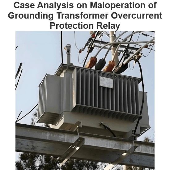
Distribution transformers step down voltage from the distribution or primary feeder voltage to the utilization voltage. They are connected to the primary feeder, sub-feeders, and laterals through primary fuses or fused cutouts. The primary fuse disconnects its associated distribution transformer from the primary feeder when a transformer fault or low-impedance secondary-circuit fault occurs. Fused cutouts, which are normally closed, provide a convenient means for disconnecting small distribution transformers for inspection and maintenance.
Satisfactory overload protection of a distribution transformer cannot be achieved with a primary fuse alone. This is due to the difference in the shape of its current-time curve and the safe current-time curve of a distribution transformer. If a small enough fuse is used to offer complete overload protection for the transformer, much of the valuable transformer overload capacity is lost as the fuse blows prematurely. Such a small fuse also frequently blows unnecessarily on surge currents. Therefore, a primary fuse should be selected based on providing short-circuit protection only, with its minimum blowing current usually exceeding 200% of the full load current of its associated transformer.
Distribution transformers connected to overhead open-wire feeders are often subjected to severe lightning disturbances. To minimize insulation breakdown and transformer failures from lightning, lightning arresters are commonly used with these transformers.
The secondary leads of a distribution transformer are typically solidly connected to radial secondary circuits, from which consumer services are tapped. This means that the transformer lacks protection against overloads and high-impedance faults on its secondary circuits. Relatively few distribution transformers are burned out by overloads, mainly because they are often not fully utilized to their overload capacity. Another factor contributing to the low number of overload-related failures is the frequent load checks and corrective measures taken before dangerous overloads occur. However, high impedance faults on their secondary circuits likely cause more distribution transformer failures than overloads, especially in areas with poor tree conditions.
Fuses in the secondary leads of distribution transformers are little more effective in preventing transformer burnouts than primary fuses, for similar reasons. The proper way to obtain satisfactory protection for a distribution transformer against overloads and high-impedance faults is by installing a circuit breaker in the secondary leads of the transformer. The tripping curve of this circuit breaker must be properly coordinated with the safe current-time curve of the transformer. The primary fuse must also be coordinated with the secondary breaker so that the breaker trips on any current that can pass through it before the fuse is damaged.
Faults on a consumer’s service connection from the secondary circuit to the service switch are extremely rare. Thus, the use of a secondary fuse at the point where the service connection taps onto the secondary circuit is not economically justifiable, except in unusual cases such as large services from underground secondaries.
Voltage Variation Considerations
Assuming a maximum voltage variation of about 10% at any consumer’s service switch, the division of this drop among the various parts of the system, at full load, may be approximately as follows:
2% voltage variation in the primary feeder between the first and last transformers
2.5% voltage variation in the distribution transformer
3% voltage variation in the secondary circuit
0.5% voltage variation in the consumer’s service connection
The fact that the voltage at the primary of the first distribution transformer cannot ordinarily be maintained exactly accounts for the other 2%.
These figures are typical for overhead systems supplying residential loads. However, they can be expected to differ significantly in underground systems where cable circuits and large distribution transformers are used, or when supplying industrial and commercial loads.
The economic size of the distribution transformer and secondary-circuit combination for any uniform load density and type of construction, at specific market prices, can be readily determined once the total allowable voltage drop in these two parts of the system is established. If the transformer is too large, the secondary circuit cost and total cost will be excessive. Conversely, if the transformer is too small, the transformer cost and total cost will be too high.
Handling Load Changes in Transformers
As in any other part of the distribution system, load change or load growth must be considered and planned for in distribution transformers and secondary circuits. Distribution transformers and secondary circuits are not installed merely to serve the loads existing at the time of installation but also to accommodate some future loads. However, it is not economical to make excessive allowance for growth.
When a distribution transformer becomes dangerously overloaded, it can be replaced by one of the next larger size if the current-carrying capacity of the secondary circuit and the overall voltage regulation permit. If not, another transformer of about the same size can be installed between the overloaded transformer and the adjacent one. This involves removing load from the overloaded transformer by connecting part of its secondary circuit and associated load to the new transformer. This also reduces the load on the secondary circuit of the overloaded transformer and improves the overall voltage regulation. In areas with reasonably uniform load, transformers may need to be installed on both sides of the overloaded transformer relatively quickly to maintain satisfactory voltage conditions and prevent overloading parts of the secondary circuit. The same result can also be achieved by installing one new transformer and relocating the overloaded transformer so that it feeds into the center of its shortened secondary circuit.
Transformer Banking for Service Improvement
With distribution transformers and secondary circuits arranged as in the typical radial configuration, any one load is supplied through only one transformer and in only one direction over the secondary circuit. Because of this, a suddenly applied load, such as when starting a motor, on a consumer’s service can cause objectionable light flicker on other consumers’ services fed from the same transformer. The increasing use of motor-driven appliances in residential areas is resulting in a significant number of light-flicker complaints. In some areas, light flicker, rather than voltage regulation, may be the determining factor in the size and arrangement of transformers and secondary circuits.
The banking of distribution transformers is usually the best and most economical means of improving or eliminating light flicker. Banking transformers means paralleling on the secondary side a number of transformers all connected to the same primary circuit. The secondary circuit arrangement in a banked transformer layout can take various forms, such as loops or grids similar to those used in a secondary network system. However, banked transformers, being connected to and supplied over a single radial-primary feeder, are a form of radial distribution system, unlike a secondary network loop or grid which is supplied over two or more primary feeders and offers much greater service reliability.
The conversion from the usual radial secondary circuit arrangement to the banked-transformer arrangement can usually be done simply and cheaply by closing the gaps between the radial secondaries of a number of transformers associated with the same primary feeder and installing the proper primary and secondary fuses.
Protection in Transformer Banking
Two major forms of protection have been used when banking distribution transformers. The first arrangement, which is probably the oldest and most common, involves connecting the distribution transformers to the primary feeder through primary fuses or fused cutouts. These fuses should blow only on a fault in their associated transformer. All transformers are connected to the common secondary circuit through secondary fuses, whose purpose is to disconnect a faulty transformer from the secondary circuit. The size of the secondary fuse must be such that it will blow on a primary fault between its transformer and the associated primary fuse. Faults on the secondary circuit are normally expected to burn themselves clear. To prevent frequent blowing of secondary fuses on secondary-circuit faults, these fuses should have relatively long blowing times on all fault currents, but not so long as to fail to provide some protection to the transformers against secondary faults that do not clear quickly.
Using a secondary breaker with proper current-time characteristics is preferable to secondary fuses when banking transformers as it offers greater protection to the transformer against overloads and high-impedance faults. The secondary fuses or breakers should open in less time than the primary fuses on any possible current to prevent the blowing of primary fuses on a secondary fault.
A transformer fault is cleared by the transformer’s primary and secondary fuses without interrupting service. Most secondary faults clear quickly, but when a secondary fault persists, several or all of the secondary fuses may blow and some transformers may be burned out. Experience shows that with careful study of expected fault currents and proper selection of primary and secondary fuses, this method of banking operates with minimal issues. However, occasionally a secondary-circuit fault causes multiple secondary fuses to blow and some transformers to burn out, resulting in a greater service interruption than with radial secondary circuits.
The second transformer banking arrangement is preferable as there is no danger of a complete service interruption to the banked area due to a secondary fault. In this arrangement, distribution transformers are connected to the primary feeder through primary fuses for the same reasons as in the first arrangement. The transformers are solidly connected to the secondary circuit, which is sectionalized between transformers by secondary fuses. These fuses are selected to blow quicker than any primary fuse for any secondary-circuit fault. When a transformer fails, it is removed from the system by its primary fuse and the adjacent secondary fuses on either side. Thus, a transformer fault results in a service interruption only for the consumers associated with the faulty transformer. A secondary-circuit fault usually burns clear, but if it persists, it is cleared by the secondary fuses next to the faulty section and the primary fuse of the associated transformer. The secondary fuses are typically selected to operate even on high-impedance faults, while the primary fuses are not, for the reasons discussed earlier regarding radial-secondary circuits. This ensures that even with a persistent high-impedance fault, the adjacent secondary fuses blow and prevent service interruption on the unaffected secondary sections, although the associated transformer may be burned out. To prevent this, a secondary breaker with a current-time curve coordinated with the safe current-time curve of the transformer can be used in the secondary leads of the transformer. When such a breaker is used, the secondary fuses must be selected so that their blowing times for all fault currents are less than the tripping times of the breakers.
Normally, the two banking arrangements function similarly. They reduce or eliminate light flicker and improve voltage regulation or allow for a reduction in the amount of transformer capacity required compared to radial-secondary circuits. This improvement is due to tying several radial-secondary circuits together and taking advantage of the diversity among different consumer groups. A significant increase in the use of banked transformers can be expected in the future, as these advantages can often be achieved at no additional cost or with a saving compared to the usual radial secondary-circuit arrangement.
In conclusion, both thermal and mechanical performance testing of distribution transformers are crucial for maintaining the reliability and longevity of these essential components in the power distribution system. By understanding their operational characteristics, implementing proper inspection and protection measures, and addressing issues such as voltage variation and load growth, we can ensure a stable and efficient power supply for consumers.
Hey there! I'm an electrical engineer specializing in Failure and Maintenance. I've dedicated my career to ensuring the seamless operation of electrical systems. I excel at diagnosing complex electrical failures, from malfunctioning industrial motors to glitchy power distribution networks. Using state - of - the - art diagnostic tools and my in - depth knowledge, I pinpoint issues quickly. On this platform, I'm eager to share my insights, exchange ideas, and collaborate with fellow experts. Let's work together to enhance the reliability of electrical setups.


