Rotor Earth Fault Protection
Rotor Earth Fault Protection Definition
Rotor earth fault protection involves methods to detect and fix faults in the rotor’s field winding to prevent damage.
Rotor Earth Fault Protection Types
Potentiometer method
AC injection method
DC injection method
Potentiometer Method
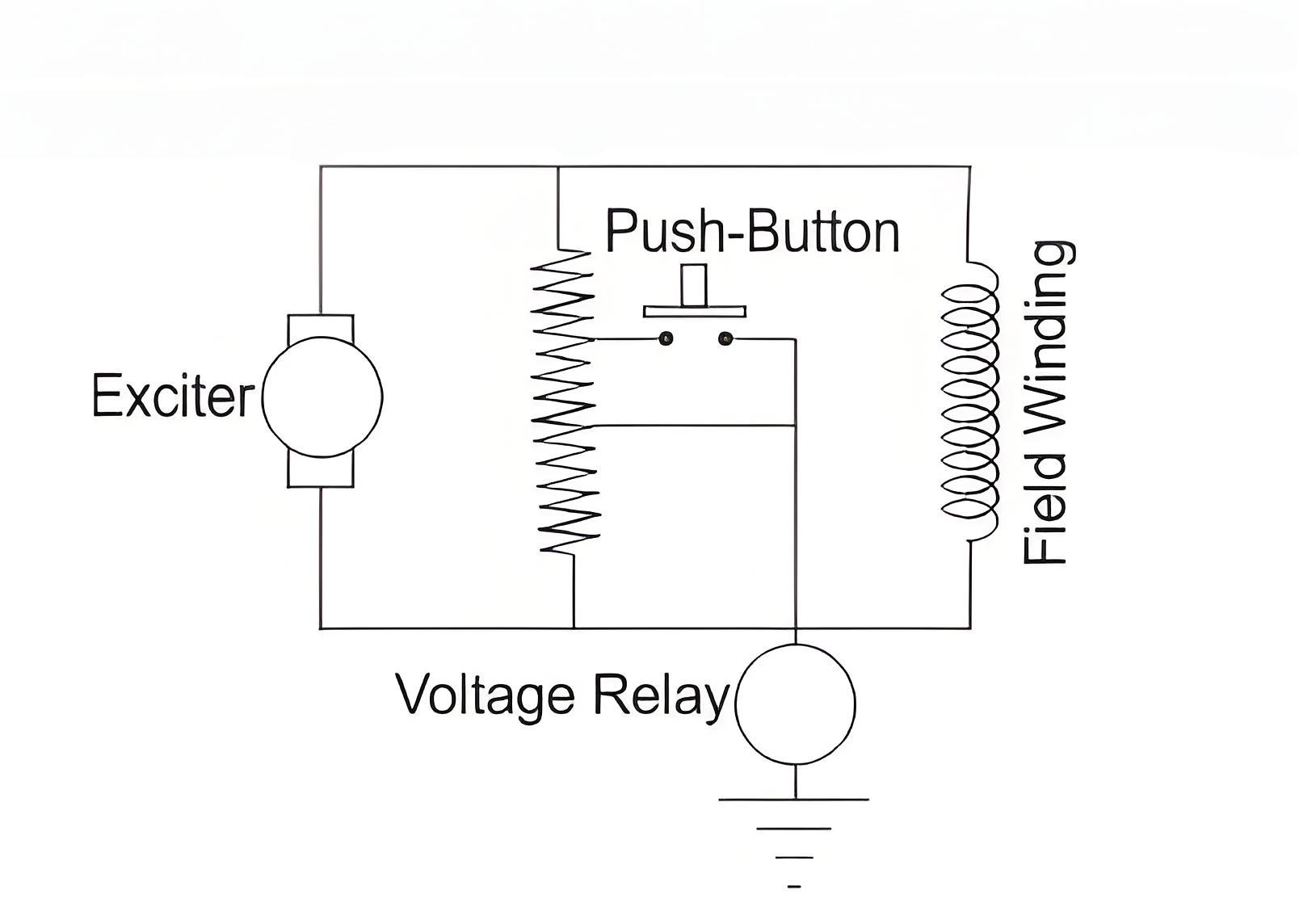
The scheme is very simple. Here, one resistor of suitable value is connected across the field winding as well as across exciter. The resistor is centrally tapped and connected to the ground via a voltage sensitive relay.
As it is seen in the figure below, any earth fault in the field winding as well as exciter circuit closes the relay circuit through earthed path. At the same time the voltage appears across the relay due to potentiometer action of the resistor.
This simple method of rotor earth fault protection has a major disadvantage. It can only detect earth faults that occur at any point except the center of the field winding.
AC Injection Method
Here, one voltage sensitive relay is connected at any point of the field and exciter circuit. Other terminal of the voltage sensitive relay is connected to the ground by a capacitor and secondary of one auxiliary transformer as shown in the figure below.
Here, if any earth fault occurs in the field winding or in the exciter circuit, the relay circuit gets closed via earthed path and hence secondary voltage of the auxiliary transformer will appear across the voltage sensitive relay and the relay will be operated.
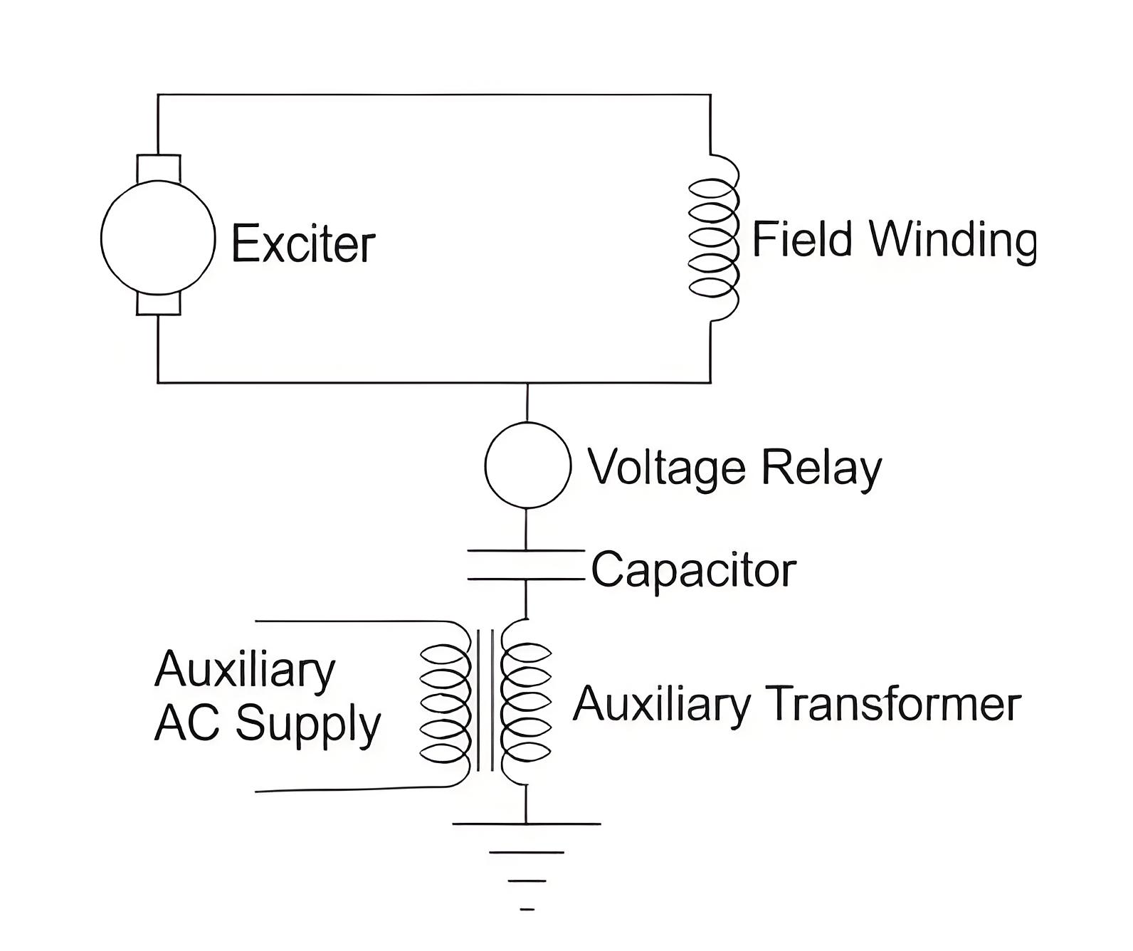
The main disadvantage of this system is, there would always be a chance of leakage current through the capacitors to the exciter and field circuit. This may cause unbalancing in magnetic field and hence mechanical stresses in the machine bearings.
Another disadvantage of this scheme is that it relies on a separate voltage source for the relay’s operation. Thus, rotor protection becomes inactive if there is a failure in the AC supply.
DC Injection Method
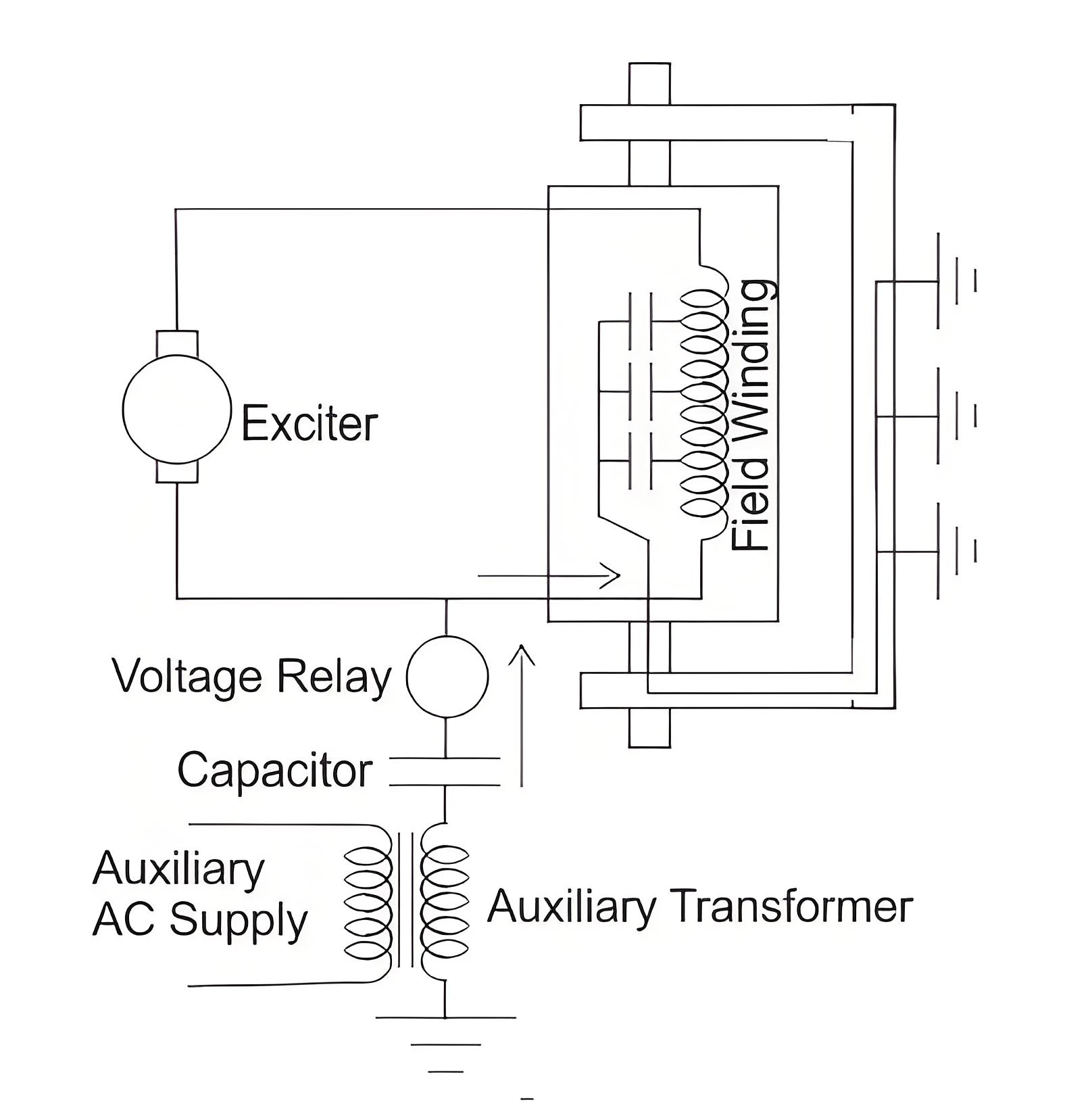
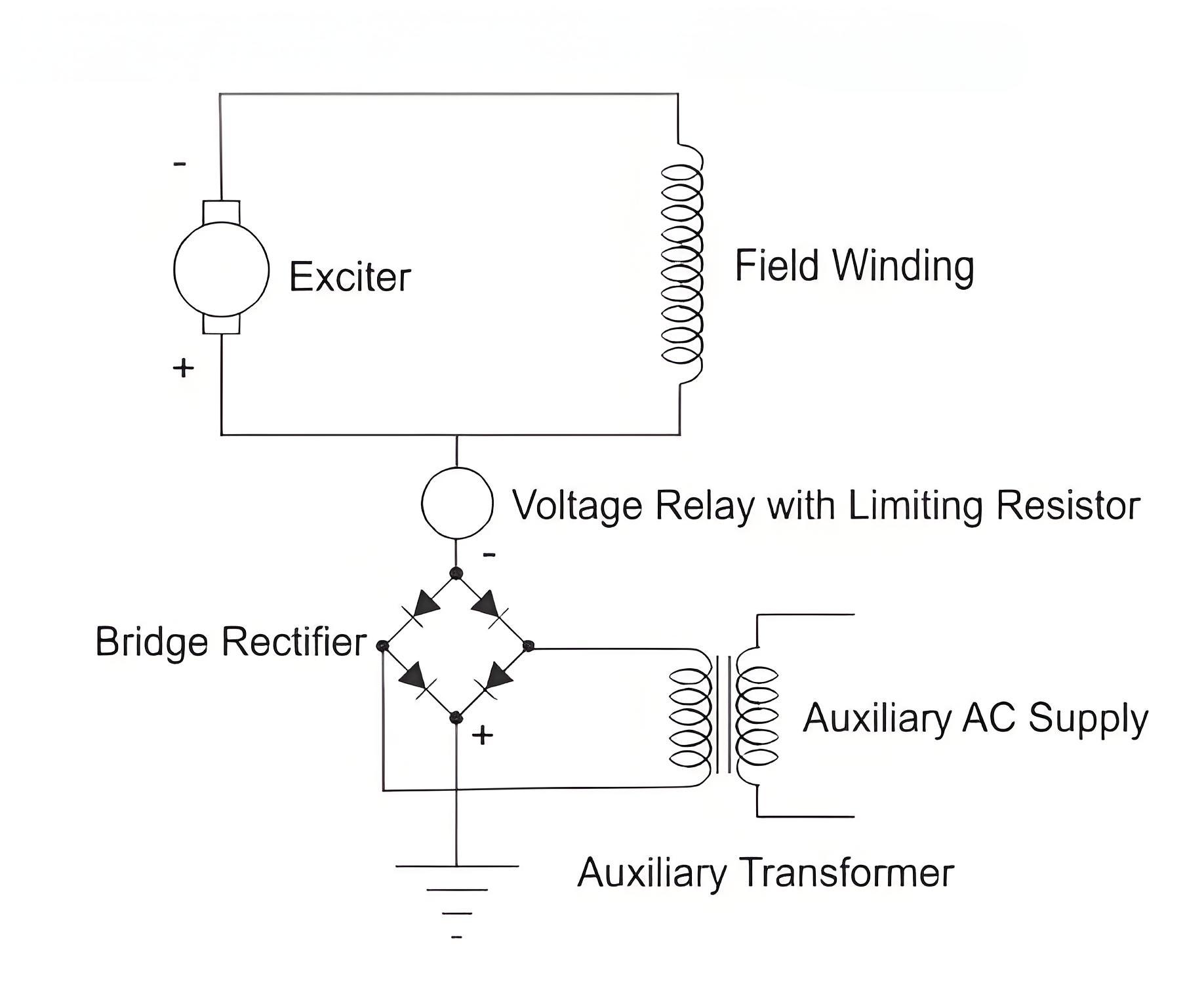
The DC injection method eliminates the leakage current problem found in the AC injection method. In this method, one terminal of a DC voltage-sensitive relay is connected to the positive terminal of the exciter, and the other terminal is connected to the negative terminal of an external DC source. This DC source is provided by an auxiliary transformer with a bridge rectifier, with its positive terminal grounded.
It is also seen from the figure below that at the event of any field earth fault or exciter earth fault, the positive potential of the external DC source will appear to the terminal of the relay which was connected to the positive terminal of the exciter. In this way the rectifier output voltage appears across the voltage relay and hence it is operated.
Importance of Detection
Detecting and rectifying rotor earth faults is crucial for preventing unbalanced magnetic fields and mechanical damage in alternators.
The Electricity Encyclopedia is dedicated to accelerating the dissemination and application of electricity knowledge and adding impetus to the development and innovation of the electricity industry.

