What is Miniature Circuit Breaker?
What is Miniature Circuit Breaker?
MCB Definition
An MCB is defined as an automatically operated switch that protects low voltage electrical circuits from excess current due to overload or short circuit.
Fuse vs MCB
Nowadays miniature circuit breakers (MCBs) are much more commonly used in low voltage electrical networks instead of fuses. The MCB has many advantages compared to a fuse:
It automatically switches off the electrical circuit during the abnormal conditions of the network (both overload and fault conditions). The MCB is much more reliable in the detection of such conditions, is it is more sensitive to change in current.
As the switch operating knob comes at its off position during tripping, the faulty zone of the electrical circuit can easily be identified. But in case of a fuse, the fuse wire should be checked by opening fuse grip or cutout from fuse base, for confirming the blow of fuse wire. Thus is it much detect if an MCB has been operated compared to a fuse.
Quick restoration of supply can not be possible in case of fuse, as fuses have to be rewirable or replaced for restoring the supply. But in the case of an MCB, quick restoration is possible by (literally) flipping a switch.
The handling of an MCB is more electrically safe than a fuse.
MCBs can be controlled remotely, whereas fuses can not.
Because of these many advantages of MCB over fuse units, in modern low voltage electrical network, the miniature circuit breaker is almost always used instead of a fuse.The only one disadvantage of MCB over fuse is that this system is costlier than a fuse unit system.
Working Principle Miniature Circuit Breaker
There are two ways an MCB operates: through the thermal effect of overcurrent and the electromagnetic effect of overcurrent. In thermal operation, a bimetallic strip heats and bends when continuous overcurrent flows through the MCB.
This deflection of the bimetallic strip releases a mechanical latch. As this mechanical latch is attached to the operating mechanism, it causes to open the miniature circuit breaker contacts.
During short circuits, the sudden rise in current causes the plunger in the tripping coil to move. This movement strikes the trip lever, immediately releasing the latch mechanism and opening the circuit breaker contacts. This explains the MCB’s working principle.
Miniature Circuit Breaker Construction
Miniature circuit breaker construction is very simple, robust and maintenance-free. Generally, an MCB is not repaired or maintained, it just replaced by a new one when required. A miniature circuit breaker has normally three main constructional parts. These are:
Frame of Miniature Circuit Breaker
The frame of a miniature circuit breaker is a molded case. This is a rigid, strong, insulated housing in which the other components are mounted.
Operating Mechanism of Miniature Circuit Breaker
The operating mechanism of a miniature circuit breaker provides the means of manual opening and closing operation of a miniature circuit breaker. It has three-positions “ON,” “OFF,” and “TRIPPED”. The external switching latch can be in the “TRIPPED” position if the MCB is tripped due to over-current.
When manually switch off the MCB, the switching latch will be in the “OFF” position. In the closed condition of an MCB, the switch is positioned at “ON”. By observing the positions of the switching latch one can determine the condition of MCB whether it is closed, tripped or manually switched off.
Trip Unit of Miniature Circuit Breaker
The trip unit is the main part, responsible for the proper working of the miniature circuit breaker. Two main types of trip mechanisms are provided in MCB. A bimetal provides protection against overload current and an electromagnet provides protection against short-circuit current.
Operation of Miniature Circuit Breaker
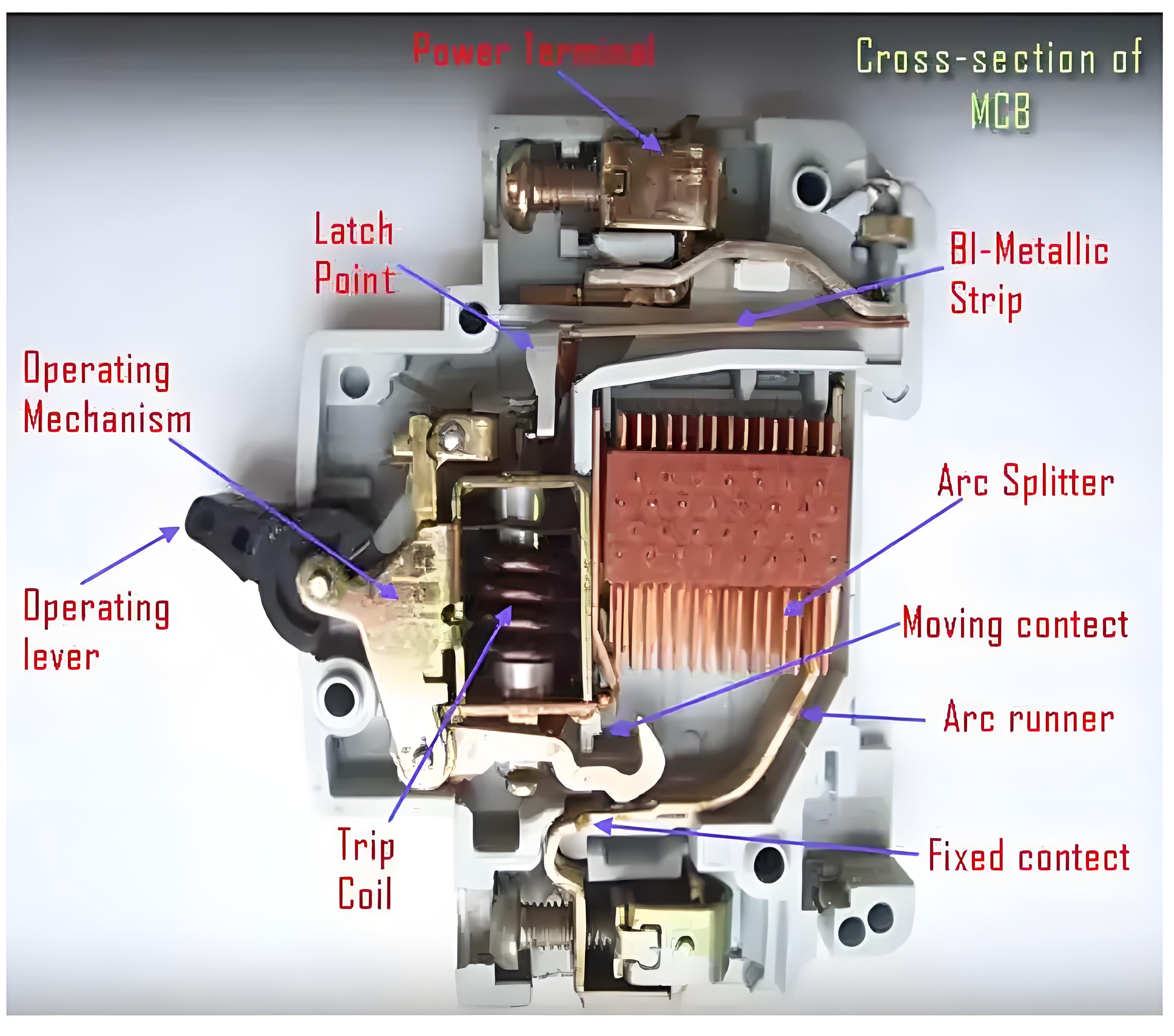
There are three mechanisms provided in a single miniature circuit breaker to make it switched off. If we carefully observe the picture beside, we will find there is mainly one bimetallic strip, one trip coil and one-hand operated on-off lever.
The electric current-carrying path of a miniature circuit breaker shown in the picture is as follows. First left-hand side power terminal – then bimetallic strip – then-current coil or trip coil – then moving contact – then fixed contact and – lastly right had side power terminal. All are arranged in series.

If the circuit is overloaded for a long time, the bimetallic strip becomes overheated and deformed. This deformation of bimetallic strip causes, displacement of latch point. The moving contact of the MCB is so arranged by means of spring pressure, with this latch point, that a little displacement of latch causes, release of spring and makes the moving contact to move for opening the MCB.
The current coil or trip coil is placed in such a manner, that during short circuit fault the MMF of that coil causes its plunger to hit the same latch point and make the latch to be displaced. Hence the MCB will open in the same manner.
Again when the operating lever of the miniature circuit breaker is operated by hand, that means when we make the MCB at off position manually, the same latch point is displaced as a result moving contact separated from fixed contact in the same manner.
Regardless of the operating mechanism – e.g. due to the deformation of the bimetallic strip, or due to the increased MMF of the trip coil, or due to manual operation – the same latch point is displaced and same deformed spring is released. This is ultimately responsible for the movement of the moving contact. When the moving contact separated from fixed contact, there may be a high chance of arc.
This arc then goes up through the arc runner and enters into arc splitters and is finally quenched. When we switch on an MCB, we actually reset the displaced operating latch to its previous on position and make the MCB ready for another switch off or trip operation.
The Electricity Encyclopedia is dedicated to accelerating the dissemination and application of electricity knowledge and adding impetus to the development and innovation of the electricity industry.


