What is a Residual Current Circuit Breaker?
What is a Residual Current Circuit Breaker?
RCCB Definition
A Residual Current Circuit Breaker (RCCB) is defined as a safety device that detects and interrupts a circuit when there is a leakage current to the ground.
Working Principle
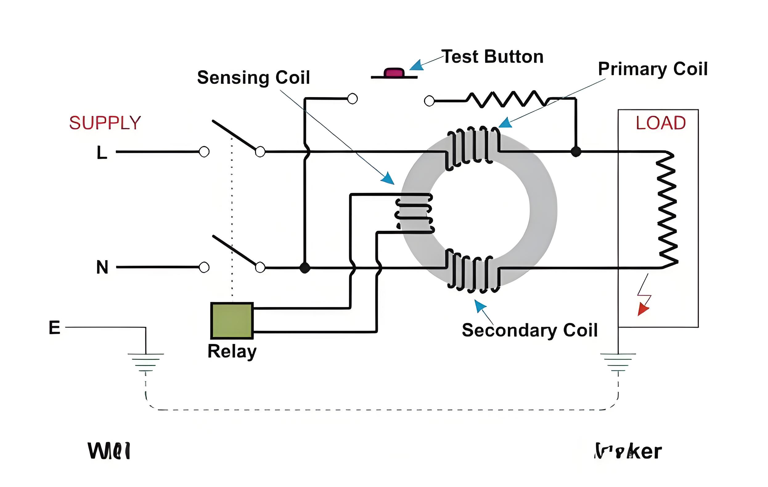
An RCCB operates based on Kirchhoff’s current law, which states that the total current entering a node equals the total current leaving it. In a normal circuit, the currents in the live and neutral wires are balanced. If there is a fault, like damaged insulation or contact with a live wire, some current flows to the ground. This imbalance is detected by the RCCB, causing it to trip and disconnect the circuit within milliseconds.
An RCCB contains a toroidal transformer with three coils: live wire, neutral wire, and sensing coil. When currents are balanced, the live and neutral coils produce equal and opposite magnetic fluxes. An imbalance generates a residual magnetic flux, inducing voltage in the sensing coil. This voltage triggers a relay to open the RCCB contacts and disconnect the circuit.

An RCCB includes a test button for users to check its functionality by creating a small leakage current. Pressing the button connects the live wire on the load side to the supply neutral, bypassing the neutral coil. This causes a current imbalance, making the RCCB trip. If it doesn’t trip, the RCCB may be faulty or incorrectly wired and needs repair or replacement.
Types of RCCBs
There are different types of RCCBs based on their sensitivity to different types of leakage currents:
Type AC: This type responds to pure alternating currents (AC) only. It is suitable for general applications where there are no electronic devices or variable frequency drives that produce direct or pulsating currents.
Type A: This type responds to both AC and pulsating direct currents (DC). It is suitable for applications where there are electronic devices such as computers, TVs, or LED lights that generate rectified or chopped currents.
Type B: This type responds to AC, pulsating DC, and smooth DC currents. It is suitable for applications where there are devices such as solar inverters, battery chargers, or electric vehicles that generate smooth DC currents.
Type F: This type responds to AC, pulsating DC, smooth DC, and high-frequency AC currents up to 1 kHz. It is suitable for applications where there are devices such as frequency converters, induction cookers, or dimmers that generate high-frequency currents.
The sensitivity of an RCCB is determined by its rated residual operating current (I∆n), the minimum leakage current needed to trip it. Common I∆n values are 10 mA, 30 mA, 100 mA, 300 mA, 500 mA, and 1 A. Lower I∆n values offer higher protection against electric shocks. For example, a 30 mA RCCB can protect against cardiac arrest if a shock lasts more than 0.2 seconds.
Another classification of RCCBs is based on their number of poles:
2-pole: This type has two slots for connecting one live wire and one neutral wire. It is used for single-phase circuits.
4-pole: This type has four slots for connecting three live wires and one neutral wire. It is used for three-phase circuits.
Advantages
They provide protection against electric shocks by detecting leakage currents as low as 10 mA.
They prevent fires and damage to equipment by interrupting faulty circuits quickly.
They are easy to install and operate with simple test and reset buttons.
They are compatible with different types of loads and currents (AC, DC, high-frequency).
They can act as main disconnecting switches upstream of any derived miniature circuit breakers (MCBs).
Disadvantages
They do not provide protection against overcurrents or short circuits, which can cause overheating and melting of wires. Therefore, they must be used in series with an MCB or a fuse that can handle the rated current of the circuit.
They may trip unnecessarily due to external factors such as lightning, electromagnetic interference, or capacitive coupling. This can cause inconvenience and loss of productivity.
They may fail to trip due to internal factors such as corrosion, wear, or mechanical jamming. This can compromise the safety of the circuit and the users.
They are more expensive and bulky than MCBs or fuses.
Choosing RCCBs
To choose the right RCCB for a circuit, the following factors should be considered:
The type of load and current: The RCCB should match the type of load (AC, DC, high-frequency) and the type of current (pure, pulsating, smooth) that it will protect. For example, a type B RCCB should be used for a solar inverter that generates a smooth DC current.
The rated residual operating current (I∆n): The RCCB should have a low enough I∆n to provide adequate protection against electric shocks, but not too low to cause nuisance tripping. For example, a 30 mA RCCB is recommended for domestic and commercial applications, while a 100 mA RCCB is suitable for industrial applications.
The rated current (In): The RCCB should have a high enough In to handle the normal operating current of the circuit, but not too high to exceed the capacity of the MCB or fuse that it is connected with. For example, a 40 A RCCB should be used with a 32 A MCB for a 230 V single-phase circuit.
The number of poles: The RCCB should have the same number of poles as the supply voltage. For example, a 2-pole RCCB should be used for a 230 V single-phase circuit, while a 4-pole RCCB should be used for a 400 V three-phase circuit.
To install an RCCB, the following steps should be followed:
Switch off the main power supply and isolate the circuit that needs to be protected by the RCCB.
Connect the live wire(s) from the supply side to the input terminal(s) of the RCCB marked as L1, L2, and L3.
Connect the neutral wire from the supply side to the input terminal of the RCCB marked as N.
Connect the live wire(s) from the load side to the output terminal(s) of the RCCB marked as L1’, L2’, and L3’.
Connect the neutral wire from the load side to the output terminal of the RCCB marked as N’.
Ensure that all connections are tight and secure and that no wires are loose or exposed.
Switch on the main power supply and test the RCCB by pressing the test button. The RCCB should trip and disconnect the circuit. If it does not, check for any wiring errors or faulty components and fix them before using the circuit.
Reset the RCCB by pressing the reset button. The RCCB should close and reconnect the circuit. If it does not, check for any wiring errors or faulty components and fix them before using the circuit.
The Electricity Encyclopedia is dedicated to accelerating the dissemination and application of electricity knowledge and adding impetus to the development and innovation of the electricity industry.


