Calculation process of maximum fuse load

Encyclopedia
09/21/2024

Calculating the maximum load of a fuse usually involves determining the rated current of the fuse and the maximum allowable current of the circuit it protects.


Procedure


Determine the rated current of the circuit


First you need to know the current required by the load in the circuit when it is working normally. This can usually be found on the device's nameplate or specification sheet.


Determine the rated current of the fuse


The rated current of the fuse means that the fuse will not blow if it does not exceed the current value. In general, the rated current of the fuse should be greater than the rated current of the circuit, but not so large that it cannot provide effective protection.


Select the appropriate fuse current rating


When selecting a fuse, the following rules are generally followed:


For purely resistive loads (such as heating equipment), the rated current of the fuse is approximately 1.15 to 1.25 times the load current.


For inductive loads (such as electric motors), the rated current of the fuse is about 2 to 2.5 times the load current, because the motor will generate a large starting current when starting.


Calculated maximum load


Calculated maximum load usually refers to the maximum current allowed in the circuit without a fuse blowing. This can be calculated by the following formula:


I max=I fuse/Safety Factor


  • Imax is the maximum allowable current of the circuit.


  • Ifuse is the rated current of the fuse.


  • The Safety Factor is a safety factor, usually 1.15 to 1.25 (for purely resistive loads) or 2 to 2.5 (for inductive loads).


Matters needing attention


  • Ambient temperature: When the ambient temperature is higher, the fuse current may be reduced.


  • Starting current: For inductive loads (such as electric motors), the starting current may be much greater than the operating current, so a fuse with a higher current rating needs to be selected.


  • Load type: Different types of loads have different requirements for the selection of fuses.


  • Safety margin: In order to ensure higher safety, a fuse slightly larger than the calculated value is usually selected.


Encyclopedia

The Electricity Encyclopedia is dedicated to accelerating the dissemination and application of electricity knowledge and adding impetus to the development and innovation of the electricity industry.
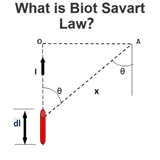
What is Biot Savart Law?
The Biot-Savart Law is employed to determine the magnetic field intensity dHnear a current-carrying conductor. In other words, it describes the relationship between the magnetic field intensity generated by a source current element. This law was formulated in 1820 by Jean-Baptiste Biot and Félix Savart. For a straight wire, the direction of the magnetic field adheres to the right-hand rule. The Biot-Savart Law is also referred to as Laplace’s law or Ampère’s law.Conside
Edwiin
05/20/2025
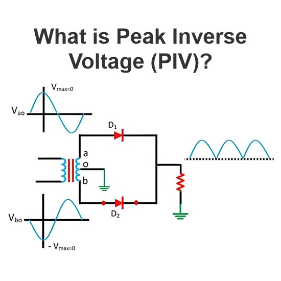
What is Peak Inverse Voltage (PIV)?
DefinitionThe maximum value of the reverse voltage that a PN junction or diode can withstand without damage is termed thePeak Inverse Voltage (PIV). This PIV rating is specified and explained in the datasheet provided by the manufacturer.However, if the voltage across the junction under reverse bias exceeds this specified value, the junction will be damaged.As shown in the figure above, a PN junction or diode is commonly used as a rectifier, i.e., to convert alternating current (AC) to direct cu
Edwiin
05/19/2025
What is Magnetoresistor?
Definition: When the resistance of certain metals and semiconductor materials changes in the presence of a magnetic field, this phenomenon is referred to as the magnetoresistance effect. The components that exhibit this effect are called magnetoresistors. Put simply, a magnetoresistor is a type of resistor whose resistance value fluctuates with the strength and direction of an external magnetic field.Magnetoresistors play a crucial role in detecting the presence of a magnetic field, measuring it
Encyclopedia
05/10/2025
How does the input voltage affect the current flowing through the load resistor in an ideal transformer?
How Input Voltage Affects the Current Through a Load Resistor in an Ideal TransformerAn ideal transformer is one that assumes no energy losses (such as copper loss or iron loss). Its primary function is to change the levels of voltage and current while ensuring that the input power equals the output power. The operation of an ideal transformer is based on the principle of electromagnetic induction, and there is a fixed turns ratio n between the primary and secondary coils, given by n=N2 /N1, whe
Encyclopedia
01/24/2025
Inquiry
Download
Experts Electrical is dedicated to serving the personnel in the global power industry.
Join Experts Electrical, not only can you discover power equipment and power knowledge, but also canhnd like - minded friends!