Scattering Parameters Tutorial: What Are They & What Do They Do?
What are S Parameters?
The S-parameters, also known as scattering or S-matrix parameters, represent how RF energy moves through a multi-port network. It represents the linear properties of RF electronic components and describes how energy travels through an electric network.
The S-parameter matrix calculates characteristics like gain, loss, impedance, phase group delay, and VSWR. S-parameters are used to represent a complex network as a simple “black box” and clearly indicate what happens to the signal within that network. The black box could contain anything, ranging from a resistor, a transmission line, or an integrated circuit.
When discussing S-parameters, the term “scattering” describes how the travelling currents and voltages in a transmission line are affected when they come into contact with a discontinuity brought on by the introduction of a network into the transmission line.
S parameters are widely employed in electrical, electronic, and communication systems engineering to effectively describe the electrical characteristics of linear electrical networks, particularly those operating at high frequencies and subject to various steady-state input signals with small amplitudes.
S-parameters can be used at any frequency, but they are primarily used in radio frequency (RF) and microwave networks because signal power and energy considerations are simpler to measure than currents and voltages. S-parameter measurements must include frequency information in addition to characteristic impedance or system impedance because S-parameters are frequency-dependent.
A network or circuit interconnects various electrical components such as resistors, inductors, and capacitors. A pair of terminals at which a signal may enter or leave a network is called a Port or any pair of terminals into which energy is supplied or from which energy is withdrawn.
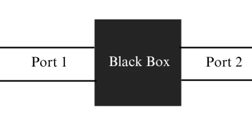
An electrical network, or “black box,” to be characterised using S parameters may have any number, N, of ports, as shown in Figure 1. Ports are the points at which electrical currents either enter or exit the network. Sometimes these are referred to as pairs of “terminals”.
What Do S-Parameters Indicate?
S-parameters are complex numbers (numbers with real and imaginary parts) that can be used either directly or in a matrix to display the amplitude and/or phase of reflection or transmission characteristics in the frequency domain.
When a complex time-varying signal is passed through a linear network, the amplitude and phase shifts can distort the time-domain waveform dramatically. As a result, amplitude and phase information in the frequency domain are critical. S-parameters are a parameter that supports both information and has many advantages for the characterization of high-frequency devices.
When specifying a set of S-parameters, the following information must be defined:
The frequency
The nominal characteristic impedance (often 50 Ω)
The allocation of port numbers
Conditions which may affect the network, such as temperature, control voltage, and bias current, where applicable
The Specifics of S-Parameters
According to the S-parameter approach, an electrical network is a “black box” that contains a variety of interconnected basic electrical circuit components, including resistors, capacitors, inductors, and transistors, and that communicates with other circuits via ports.
The S-parameter matrix, which can be used to determine the network’s response to signals applied to the ports, is a square matrix of complex numbers that serves as a characteristic of the network. An electrical network described by S-parameters may have a number of ports.
S parameters offer a versatile means of expressing various electrical attributes of networks or components, including parameters like gain, return loss, voltage standing wave ratio (VSWR), network stability, and reflection coefficient.
Source: Electrical4u.
Statement: Respect the original, good articles worth sharing, if there is infringement please contact delete.
Electrical4U is dedicated to the teaching and sharing of all things related to electrical and electronics engineering.
