Cutset Matrix Concept of Electric Circuit

When we talk of cut set matrix in graph theory, we generally talk of fundamental cut-set matrix. A cut-set is a minimum set of branches of a connected graph such that when removed these branches from the graph, then the graph gets separated into 2 distinct parts called sub-graphs and the cut set matrix is the matrix which is obtained by row-wise taking one cut-set at a time. The cutset matrix is denoted by symbol [Qf].
Example of Cutsets Matrix of a Circuit
Two sub-graphs are obtained from a graph by selecting cut-sets consisting of branches [1, 2, 5, 6].
Thus, in other words we can say that fundamental cut set of a given graph with reference to a tree is a cut-set formed with one twig and remaining links. Twigs are the branches of tree and links are the branches of co-tree.
Thus, the number of cutset is equal to the number of twigs.
[Number of twigs = N – 1]
Where, N is the number of nodes of the given graph or drawn tree.
The orientation of cut-set is the same as that of twig and that is taken positive.
There are some steps one should follow while drawing the cut-set matrix. The steps are as follows-
Draw the graph of given network or circuit (if given).
Then draw its tree. The branches of the tree will be twig.
Then draw the remaining branches of the graph by dotted line. These branches will be links.
Each branch or twig of tree will form an independent cut-set.
Write the matrix with rows as cut-set and column as branches.
| Branchase ⇒ | 1 | 2 | 3 | . | . | b | |
| Cutsets | |||||||
| C1 | |||||||
| C2 | |||||||
| C3 | |||||||
| . | |||||||
| . | |||||||
| Cn | |||||||
n = number of cut-set.
b = number of branches.
Orientation in Cut Set Matrix
Qij = 1; if branch J is in cut-set with orientation same as that of tree branch.
Qij = -1; if branch J is in cut-set with orientation opposite to that of branch of tree.
Qij = 0; if branch J is not in cut-set.
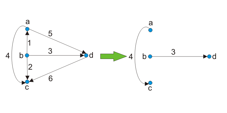
Example 1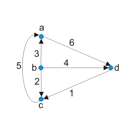
Draw the cut-set matrix for the following graph.
Answer:
Step 1: Draw the tree for the following graph.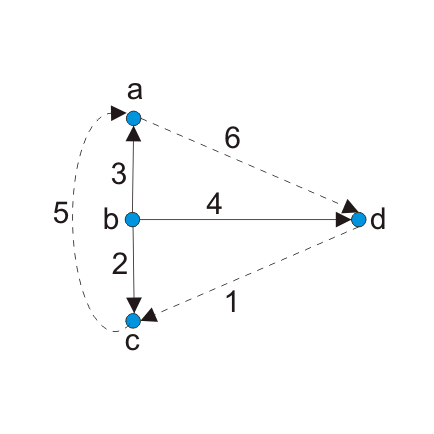
Step 2: Now identify the cut-set. Cut-set will be that node which will contain only one twig and any number of links.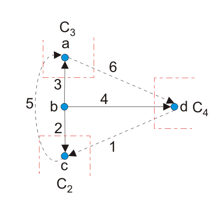
Here C2, C3 and C4 are cut-sets.
Step 3: Now draw the matrix.
| Branchase ⇒ | 1 | 2 | 3 | 4 | 5 | 6 | |
| Cutsets | |||||||
| C2 | +1 | +1 | 0 | 0 | -1 | 0 | |
| C3 | 0 | 0 | +1 | 0 | +1 | -1 | |
| C4 | -1 | 0 | 0 | +1 | 0 | +1 |
|
This is the required matrix.
Example 2: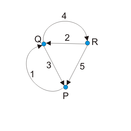
Draw the cut-set of the given graph.
Answer:
Again in this question we have to repeat the same steps as done in previous question.
Step 1: Draw the tree for the following graph.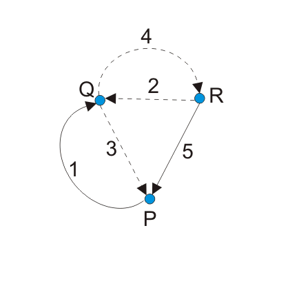
Step 2: Now identify the cut-set. Cut-set will be that node which will contain only one twig and any number of links.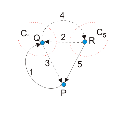
Here C1 and C5 are cut-sets.
Step 3: Now draw the matrix.
| Branchase ⇒ | 1 | 2 | 3 | 4 | 5 | |
| Cutsets | ||||||
| C1 | +1 | +1 | -1 | -1 | 0 | |
| C5 | 0 | -1 | 0 | -1 | +1 | |
This is the required matrix.
Points to remember
There are some key points which should be remembered. They are:-
In cutset matrix, the orientation of twig is taken positive.
Each cut-set contains only one twig.
Cut-set can have any number of links attached to it.
The relation between cut-set matrix and KCL is that

Source: Electrical4u.
Statement: Respect the original, good articles worth sharing, if there is infringement please contact delete.
Electrical4U is dedicated to the teaching and sharing of all things related to electrical and electronics engineering.