Dual Network Circuit Analysis

Electrical4u
03/12/2024

What is a Dual Network?

Two electrical networks are said to be dual networks if the mesh equations of one network is equal to the node equation of the other.

The dual network is based on Kirchhoff Current Law and Kirchhoff Voltage Law.

electric mesh network

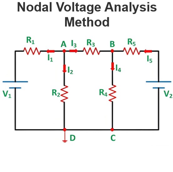
Applying Kirchhoff Voltage Law in the network A, above we get,

electric node network

Applying Kirchhoff Current Law in the network B, above we get,

Here we have found that equations (i) and (ii) are similar in their mathematical form. Equation (i) is in mesh form and equation (ii) is in nodal form.

Here, the left side variable of equation (i) is voltage, and the left side variable of equation (ii) is current.

Similarly, the right side of equation (i) is a product of the current and total impedance of the circuit.

Similarly, the right side of equation (ii) is the product of voltage and admittance of the circuit.

So, it is needless to say these two networks are dual networks. From, the examples it is also clear that dual networks may not be equivalent networks.

The circuit equation of the two dual networks are similar in form but the variable is interchanged.

Construction of a Dual Network

Let us consider the series RLC circuit as shown below.

series rlc circuit

Applying Kirchhoff Voltage Law in this circuit, we get,

Let us replace all the variables and constants by their dual in the equation. By doing that, we get,

The electrical network drawn by the circuit equation (iv), would be

parallel rlc circuit

Hence:

This is nothing but Kirchhoff’s Current Law. As per the definition of a dual network, network C and network D are dual to each other.

Table of Dual Elements

Element Element
Electrical resistance Conductance
Inductance Capacitance
Service Branch Parallel Branch
Switch Closed Switch Open
Charge Flux Linkage
Mesh Node

Source: Electrical4u.

Statement: Respect the original, good articles worth sharing, if there is infringement please contact delete.


Electrical4u

Electrical4U is dedicated to the teaching and sharing of all things related to electrical and electronics engineering.

Current Division and Voltage Division Rule
Current Division RuleA parallel circuit functions as a current divider, where the incoming current splits among all branches while the voltage across each branch remains constant. The Current Division Rule is used to determine the current through circuit impedances, as illustrated by the circuit below:The currentI splits intoI1 andI2 across two parallel branches with resistancesR1 andR2, whereVdenotes the voltage drop across both resistances. As is known,Then the equation of the current is writt
Edwiin
06/02/2025
Mesh Current Analysis Method
The Mesh Current Analysis Method is utilized to analyze and solve electrical networks with multiple sources or circuits comprising numerous meshes (loops) containing voltage or current sources. Also known as the Loop Current Method, this approach involves assuming a distinct current for each loop and determining the polarities of voltage drops across loop elements based on the assumed direction of the loop current.In mesh current analysis, the unknowns are the currents in different meshes, and t
Edwiin
06/02/2025
Nodal Voltage Analysis Method
Nodal Voltage AnalysisNodal voltage analysis is a method for solving electrical networks, particularly useful when all branch currents need to be computed. This approach determines voltages and currents by leveraging the nodes of a circuit.Anodeis a terminal where three or more circuit elements connect. Nodal analysis is commonly applied to networks with multiple parallel circuits sharing a common ground terminal, offering the advantage of requiring fewer equations to solve the circuit.Principle
Edwiin
06/02/2025
Series Magnetic Circuit
Definition of Series Magnetic CircuitDefinition: A series magnetic circuit is defined as a magnetic pathway composed of multiple sections with varying dimensions and materials, all carrying the same magnetic field. Consider a circular coil or solenoid with distinct dimensional parameters, as illustrated in the figure below:Series Magnetic Circuit AnalysisA currentIflows through a solenoid withNturns wound around one section of a circular coil, inducing a flux Φ in the core.a₁, a₂, a₃: Cross-
Edwiin
05/28/2025
Inquiry
Download
Experts Electrical is dedicated to serving the personnel in the global power industry.
Join Experts Electrical, not only can you discover power equipment and power knowledge, but also canhnd like - minded friends!