What is the Ferranti Effect?
What is the Ferranti Effect?
Ferranti Effect Definition
The Ferranti effect is defined as the increase in voltage at the receiving end of a long transmission line compared to the sending end. This effect is more noticeable when the load is very small or there is no load (open circuit). It can be described as a factor or a percentage increase.
In general practice, current flows from higher potential to lower potential to balance the electrical potential difference. Usually, the sending end voltage is higher than the receiving end because of line losses, so current flows from the supply end to the load.
But Sir S.Z. Ferranti, in the year 1890, came up with an astonishing theory about medium transmission line or long-distance transmission lines suggesting that in case of light loading or no-load operation of the transmission system, the receiving end voltage often increases beyond the sending end voltage, leading to a phenomenon known as Ferranti effect in a power system.
Ferranti Effect in Transmission Line
A long transmission line has significant capacitance and inductance along its length. The Ferranti effect occurs when the current drawn by the line’s capacitance is greater than the load current at the receiving end, especially during light or no load conditions.
The capacitor charging current causes a voltage drop across the line inductor, which is in phase with the sending end voltage. This voltage drop increases along the line, making the receiving end voltage higher than the sending end voltage. This is known as the Ferranti effect.

Thus both the capacitance and inductor effect of transmission line are equally responsible for this particular phenomena to occur, and hence Ferranti effect is negligible in case of a short transmission line as the inductor of such a line is practically considered to be nearing zero. In general for a 300 Km line operating at a frequency of 50 Hz, the no-load receiving end voltage has been found to be 5% higher than the sending end voltage.
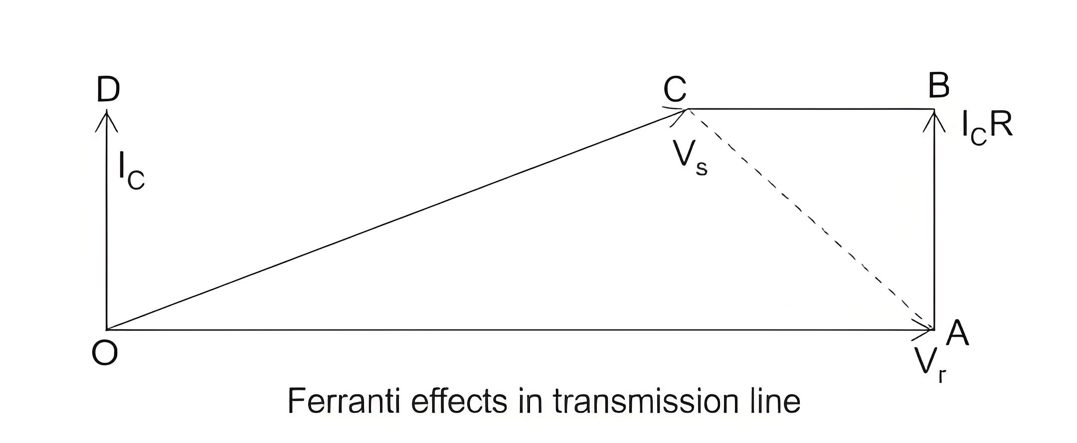
Now for the analysis of the Ferranti effect let us consider the phasor diagrams shown above.
Here, Vr is considered to be the reference phasor, represented by OA.

This is represented by the phasor OC.
Now in case of a “long transmission line,” it has been practically observed that the line electrical resistance is negligibly small compared to the line reactance. Hence we can assume the length of the phasor Ic R = 0; we can consider the rise in the voltage is only due to OA – OC = reactive drop in the line.
Now if we consider c0 and L0 are the values of capacitance and inductor per km of the transmission line, where l is the length of the line.

Since, in case of a long transmission line, the capacitance is distributed throughout its length, the average current flowing is,


From the above equation it is absolutely evident, that the rise in voltage at the receiving end is directly proportional to the square of the line length, and hence in case of a long transmission line it keeps increasing with length, and even goes beyond the applied sending end voltage at times, leading to the phenomena called Ferranti effect. If you’d like to be quizzed on the Ferranti effect and related power system topics, check out our power system MCQ (Multiple Choice Questions).
It is clear that the voltage rise at the receiving end is directly proportional to the square of the line length. In long transmission lines, this increase can even exceed the sending end voltage, leading to the Ferranti effect. If you want to test your knowledge, check out our power system MCQ (Multiple Choice Questions).
The Electricity Encyclopedia is dedicated to accelerating the dissemination and application of electricity knowledge and adding impetus to the development and innovation of the electricity industry.


