What is Electromagnetic Interference ?
What is Electromagnetic Interference ?
Definition of Electromagnetic Interference
Electromagnetic interference (EMI) is defined as a disturbance affecting an electrical circuit due to electromagnetic induction or radiation.
Electromagnetic interference (EMI) is defined as a disruption in an electrical circuit due to electromagnetic induction or external electromagnetic radiation. It occurs when the electromagnetic fields from one device interfere with another device.
Electromagnetic (EM) waves are created when an electric field interacts with a magnetic field. They travel at a speed of 3.0 × 10^8 m/s in a vacuum. EM waves can move through air, water, solids, or even a vacuum.
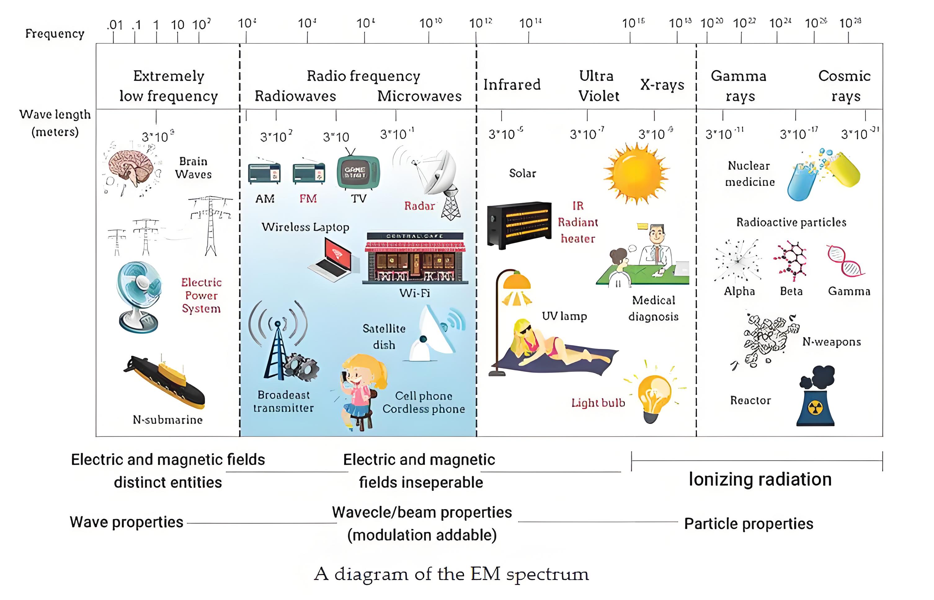
The figure below shows the EM spectrum used to represent diverse types of EM energy according to their frequencies (or wavelengths). EMI is confronted by all of us in our daily life and is anticipated to face exponential inflation in the future due to the growing numbers of wireless devices and standards, including cell phones, GPS, Bluetooth, Wi-Fi, and near-field communication (NFC).
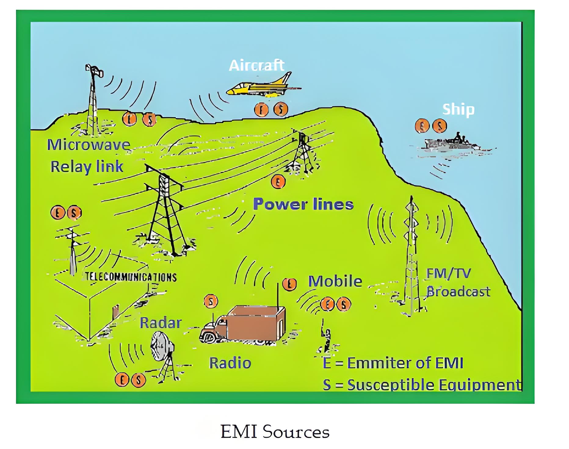
EMI can happen across a wide range of the electromagnetic spectrum, including radio and microwave frequencies. It disturbs other electrical devices. Any device with rapidly changing electrical currents can produce electromagnetic emissions.
So, the emission from one object “interferes” with another object’s emission. When one EMI interferes with another, it results in distortion of Electromagnetic Fields. Electromagnetic radiation can interfere and disturb each other even if they are not on the same frequency. This interference can be heard in radios when frequencies are switched and in TV when the signal gets distorted, the picture becomes disturbed. Henceforth, in the radio frequency spectrum, EMI is also known as Radio Frequency Interference.
EMI can easily affect the functioning of an electronic device. In general, since there is a flow of electricity through the circuits in electronic devices, it tends to create some amount of electromagnetic radiation. The energy created from device 1 gets propagated through the air as radiation or to gets coupled into cables of device 2. This results in the malfunctioning of device 2. The energy from device 1 that interferes with device 2 operation is known as Electromagnetic interference.
Causes of EMI
EMI can come from various sources including natural events like lightning and human-made sources like industrial equipment.
Transmission from TV
Radio AM, FM, and Satellite
Solar magnetic storm
Lightning that flashes as high voltage and high current
Aiport radar, Electrostatic Discharge, and White Noise
Switching mode power supplies
Arc welders, Motor Bushes, and Electrical Contacts
Types of EMI
Human-made EMI
Human-made EMI occurs from another manufactured electronic device. This type of interference happens when two signals come close to each other or when multiple signals pass through one device at the same frequencies. A good example is when the radio in the car picks up two stations simultaneously.
Natural EMI
This type of EMI also affects the devices, but they are not human-made, rather the EMI happens due to natural phenomena on earth and space like Lightning, Electric Storms, cosmic noise, etc.
The second method of classification is based on the duration of EMI. Duration of interference means the period of time for which the device experiences interference.
Continous EMI
When a source continuously emits EMI it is known as continuous EMI. The source can be human-made or natural. EMI occurs as a long coupling mechanism exists between EMI source and receiver. This type of EMI arises from sources like a circuit that emits a continuous signal.
Impulse EMI
These types of EMI occur for a very short duration like pulses. So, it is known as Impulse EMI. The source can be either natural or human-made like the continuous type of EMI. Good examples to understand are noise heard from switches, lighting, etc which emit signals that could cause a disturbance in voltage and current.
The third method of classification is based on the bandwidth of EMI. The bandwidth of EMI refers to the frequency range experienced by EMI. Based on this EMI is divided into two types as Narrowband and Broadband EMI.
Narrowband EMI
This type of EMI occurs at a single frequency that gets generated from an oscillator. It can also occur due to different types of distortion in a transmitter. Usually, in the communication system, narrowband EMI plays a very minor role and it can be corrected easily. But, the limit of interference should be controlled in limits.
Broadband EMI
The main difference from that of the narrowband EMI is that this type of EMI does not occur at a single frequency. When looking at the magnetic spectrum, this type of EMI covers a wide spectrum and exists in different forms. The source can be either natural or human-made. An example of a human-made source is an arc welding, in which spark is emitted continuously. Similarly, an example of a natural source is Sun-outs for a satellite TV system.
EMI Coupling Mechanisms
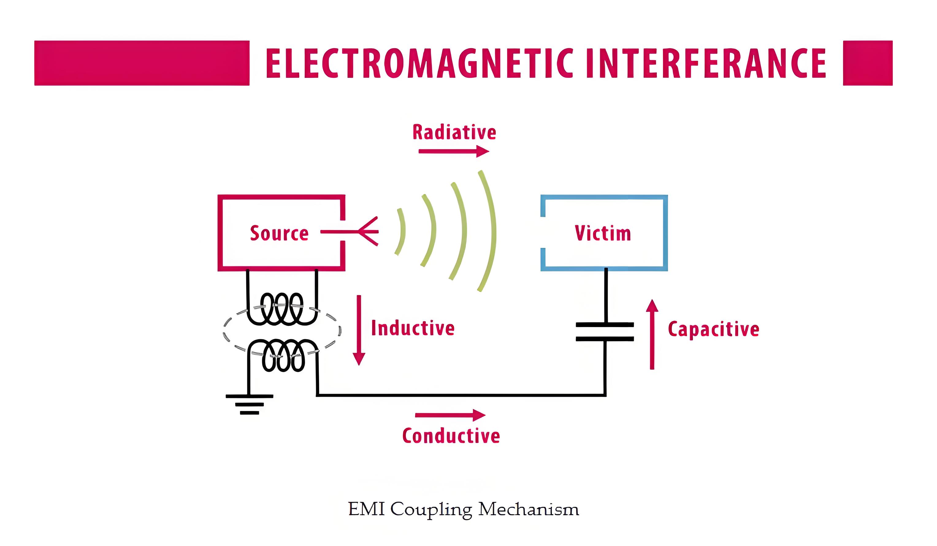
The coupling mechanism of EMI helps to understand how EMI is generated from the source and reaches the receiver. To rectify the problems that occur due to EMI, the nature of EMI, and how it is coupled from source to receiver has to be clearly understood. Few types of coupling are Conduction, Radiation, Capacitive, and Inductive coupling. By understanding the coupling mechanisms, EMI can be reduced by taking measures to reduce the coupling and level of interference.
Conduction Coupling
Conduction coupling happens when EMI emissions travel alone the conductor, wires, and cables that connect the source and receiver. When there is conduction along the route in which the signals travel, conducted emissions occur and this is understood as conducted EMI. It can appear along the power lines or any interconnection cable. Conduction can happen in one of two modes,
Common Mode
EMI occurs when noise develops in the same phase when two conductors are used. Eg: +ve and -ve of a power cable
Differential Mode
When two conductors are used, when the noise is out of phase on the conductors, it is said to operate in differential mode.
Radiation Coupling
The most common type of coupling that occurs when the source and receiver are separated by a large distance that is more than a wavelength. There is no physical contact between the source and receiver since the EMI is radiated via space to the receiver. Henceforth, when the unwanted signal is transferred from source to receiver by radiation technique through space, it is known as Radiated EMI.
Capacitive Coupling
This type of coupling is achieved between two connected devices. It occurs when a voltage that changes from a source, capacitively transfers the charge to the victim.
Inductive Coupling
When a conductor induces interferences in another conductor that is placed nearby based on the principle of electromagnetic induction, it produces EMI known as Magnetic coupled EMI. In simple terms, when a varying magnetic field is present between source and victim, a sufficient amount of current will be induced in the victim circuitry. This results in signal transfer from the source to the victim.
EMI Coupling Mechanisms
EMI can transfer from a source to a receiver through conduction, radiation, capacitive, and inductive coupling.
Reducing EMI
Earth ground
In industries, the signals and return currents are carried using ground systems. They also form the references for analog and digital circuits, thereby protecting the human and equipment from fault and lightning. When current flows in the grounding system, it causes the potential differences.
When lightning strikes, it causes a potential difference in units of thousand volts. Right from the beginning of circuit design, the ground system should be considered such that the system works with required safety requirements. When sketching a ground or troubleshooting a ground problem, it is first required to ascertain where the current is passing.
When various kinds of grounds coincide, the current may not return by the assumed path. Proper grounding depends on several factors such as the frequencies and impedances, the length of cabling required, and safety issues.
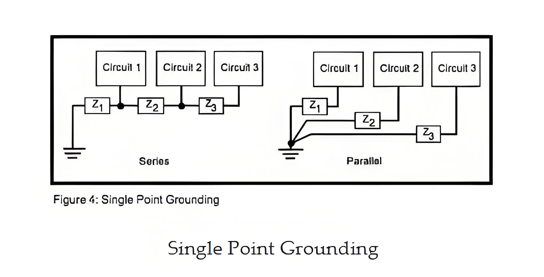
The most beneficial type of ground for low-frequency applications is the single-point ground as shown in the figure below. When sensitive circuitry or cabling is used the series connection or daisy chain, should be avoided because return currents from the three circuits flow through the common ground impedances linking the circuits.
From the figure, it is seen that the ground potential of circuit 1 is not only defined by its return current through impedance Z1 but also by the return currents from circuits 2 and 3 throughout the same impedance. This influence is called common-impedance coupling and is a fundamental means of noise coupling.
To avoid this problem, a parallel connection is preferred for grounding. It is usually more complicated and more expensive to implement because of the amount of wiring required. Most systems utilize a blend of both topologies.
Shielding
There are numerous factors that worsen EMI and there are also some ways to lessen EMI and able to pass the standards. One of the particular ways to combat EMI is through shielding. Shielding is a method of decreasing and regulating the coupling of radio waves, electromagnetic fields, and electrostatic fields.
Shielding is implemented to confine electrical devices from the ‘outside world’, and to cables to separate wires from the environment through which the cable runs. The effectiveness of a shield depends on the three factors; reflections, absorption, and multiple reflections.
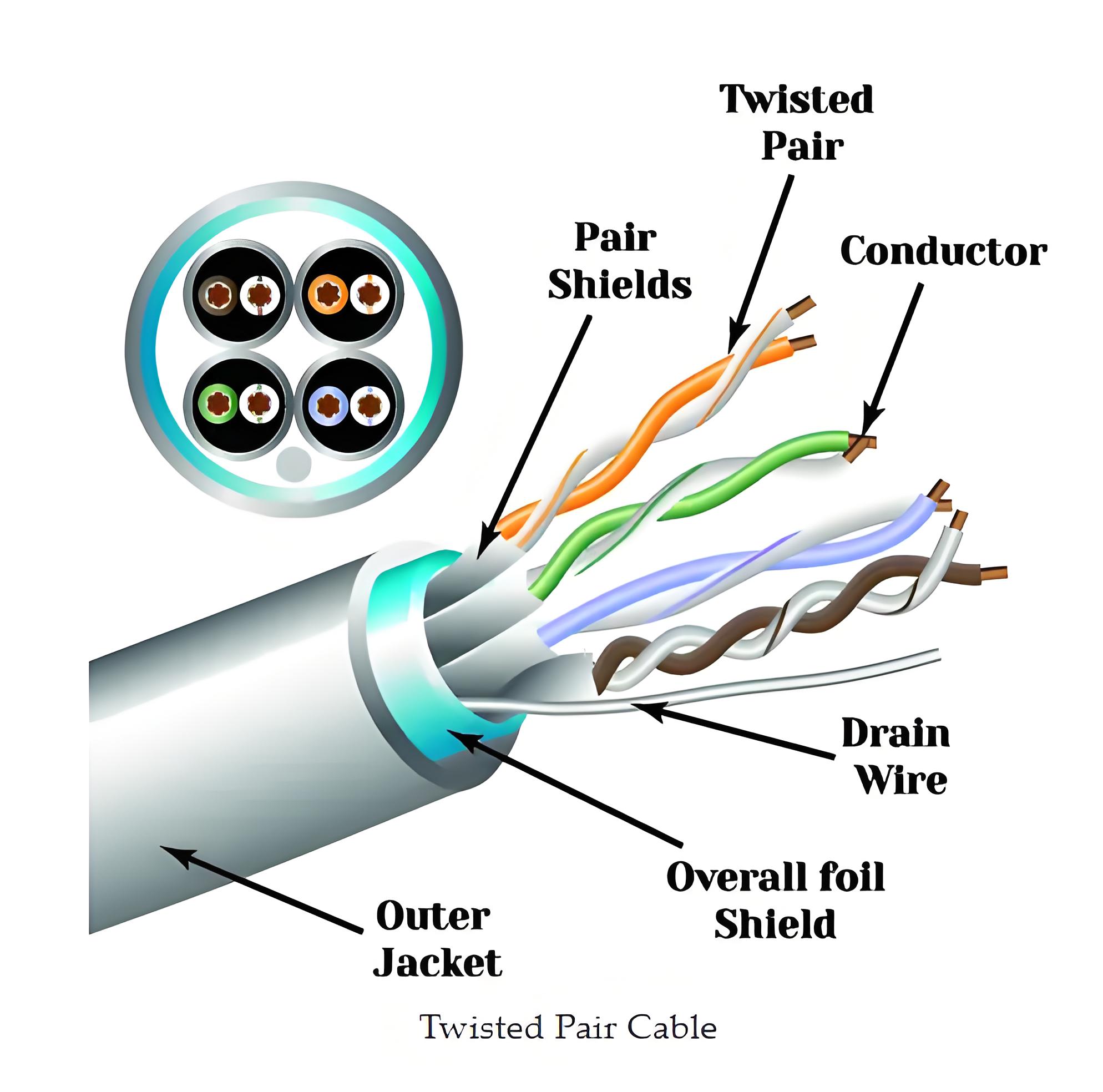
The electrical cables that contain insulating conductors encased in a standard conductive layer are understood as shielded cables. The shield can be made of strands of braided copper (or a similar metal), a spiral copper tape, or some additional conducting polymer. Shielded cables are regularly thicker and more rigorous than unshielded cables. They also require more comprehensive care when working with them.
Unshielded, twisted cables do not have internal shielding to reduce EMI. Alternatively, they are meant to cancel out EMI by employing a twisted pair of wires. These cables are lightweight and thin, making them best agreed for indoor applications in an office setting for a LAN or similar network cable systems.
Shielded cables are regularly thicker and more rigorous than unshielded cables. They also require more comprehensive care when working with them. Unshielded, twisted cables do not have internal shielding to reduce EMI. Alternatively, they are meant to cancel out EMI by employing a twisted pair of wires. These cables are lightweight and thin, making them best agreed for indoor applications in an office setting for a LAN or similar network cable systems.
The Electricity Encyclopedia is dedicated to accelerating the dissemination and application of electricity knowledge and adding impetus to the development and innovation of the electricity industry.

