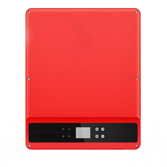
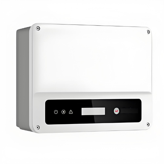
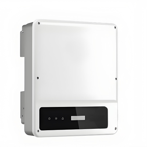
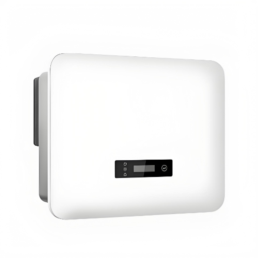
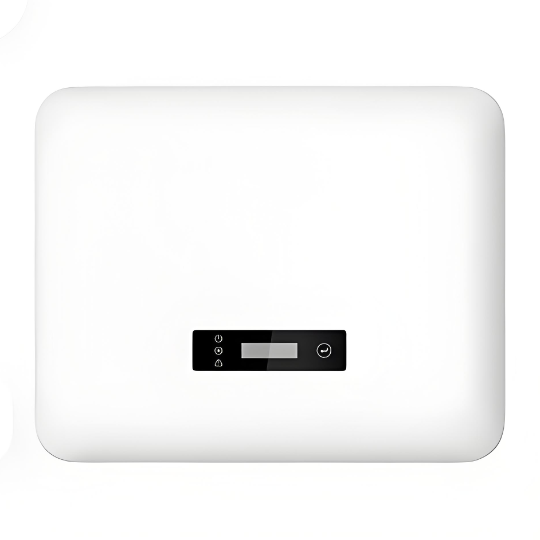
8-30kW Three Phase 2 MPPTs Residential Grid-tied Inverters
discuss personally
Model
| Brand | Wone |
| Model NO. | 8-30kW Three Phase 2 MPPTs Residential Grid-tied Inverters |
| weight | 14.7Kg |
| Max.Input Voltage | 1100V |
| Max. Input Current per MPPT | 22A |
| Number of MPP trackers | 2 |
| Nominal Output Voltage | 230/400V |
| Series | Residential Grid-tied Inverters |
Description:
The SDT G3 Series, with a power range of 8-30kW, is specifically engineered to cater to the energy needs of three-phase residential and small commercial projects. The inverter boasts an impressive 150% DC oversizing and 110% AC overloading capabilities, allowing for maximum performance and output even in challenging environments. In addition, the SDT G3 Series inverter's lightweight and easy-to-install design offers exceptional convenience for operators and installers alike.
Feature:
Smart Control & Monitoring
24/7 load consumption monitoring.
Export power limit.
Friendly & Thoughtful Design
Fanless cooling for quiet operation.
Elegant and compact design.
Superb Safety & Reliability
Optional AFCI.
IP66 ingress protection .
Optional Type II SPD on both AC and DC sides.
Flexible & Adaptable Applications
Up to 150% DC input oversizing & 110% AC output overloading .
Max. 22A DC input current per string.
Optional PID recovery.
System Parameters:


What is PID?
Definition:
A PID controller is an algorithm in a closed-loop control system used to regulate the process variables (such as temperature, pressure, flow rate, etc.) of the controlled object to keep them around the setpoint (Setpoint, SP). The PID controller calculates the deviation between the current measured value (Process Variable, PV) and the setpoint, and adjusts the control quantity (such as valve opening, heater power, etc.) according to the magnitude, duration, and rate of change of the deviation, thereby achieving precise control of the controlled object.