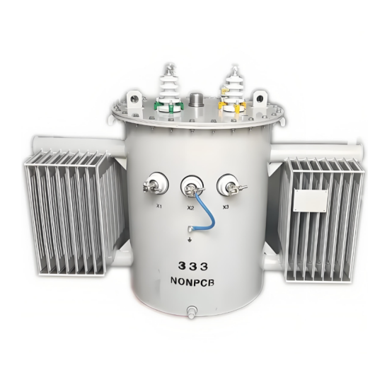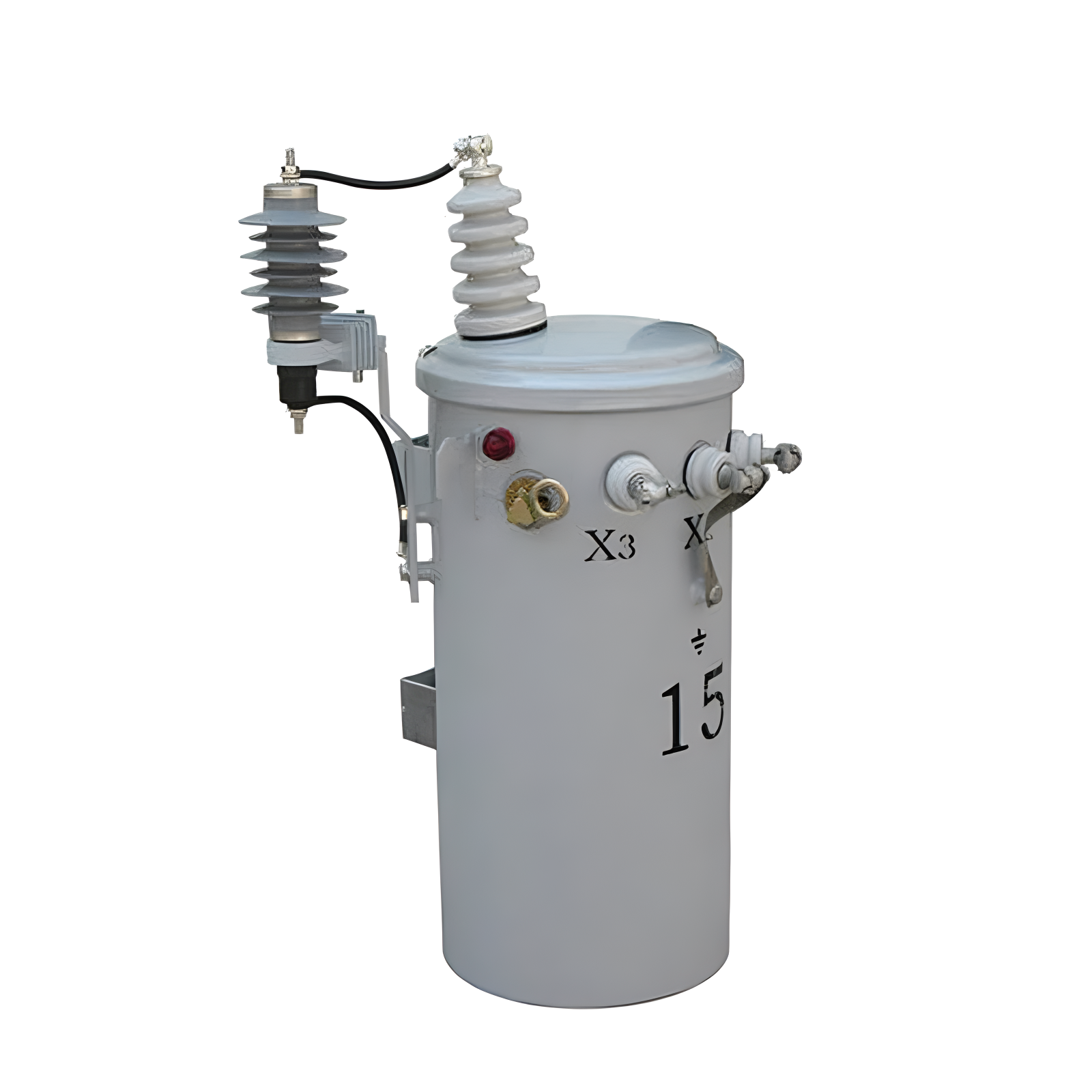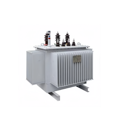
100kVA 15kV 3 Phase Oil-immersed distribution transformer
$8848.00
Model
S-M-15KV-100KVA
S-15KV-0.4KV-25KVA
S-30KV-0.4KV-500KVA
S-M-15KV-0.4KV-160KVA
S-15KV-0.4KV-250KVA
S-15KV-0.4KV-2000KVA
S-15KV-0.4KV-500KVA
S-15K-1000KVA
S-M-30KV-50KVA
S-M-30KV-0.4KV-25KVA
S-M-20KV-250KVA
S-M-15KV-50KVA
S-30KV-0.4KV-630KVA
S-M-30KV-1000KVA
S-30KV-400KVA
S-M-30KV-160KVA
S-M-30KV-100KVA
S-M-30KV-50KVA
S-15KV-25KVA
S-M-30KVA-100KVA
S-M-30KV-0.4KV-50KV
S-M-30KV-0.4KV-100KVA
S-M-33KV-0.4KV-50KVA
S-M-30KV-0.4KV-25KVA
RCW-380V
S-M-15Kv-0.4KV-100KVA