Power electronic transformer with adaptive PLL technique for voltage-disturbance ride through
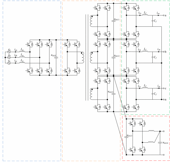
A novel PET for a distribution grid called a flexible power distribution unit is proposed in this paper, and the energy exchange mechanism between the network and the load is revealed. A 30 kW 600 VAC/220 VAC/110 VDC medium-frequency isolated prototype is developed and demonstrated. This paper also presents key control strategies of the PET for electrical distribution grid applications, especially under grid voltage disturbance conditions. Moreover, stability issues related to the grid-connected three-phase PET are discussed and verified with an impedance-based analysis. The PET prototype is tested, and it passes the voltage-disturbance ride-through function.
1.Introduction.
A distribution transformer is the most important and common equipment in a power distribution network, which is responsible for voltage transformation and voltage isolation. A traditional distribution transformer is very reliable; however, it is bulky and cumbersome. The harmonics between the primary and secondary sides cannot be isolated, and extra equipment is needed to monitor and protect for possible breakdown issues. Nowadays, these drawbacks are real concerns in academia and the industry. Therefore, power-electronics-based transformers called power electronic transformers, intelligent universal transformers, solid-state transformers, smart transformers, energy routers, and others have gradually become an emerging topic over the last 10 years, especially for aerospace, railway traction, smart grid, and Energy Internet applications . Their initial use may be in special applications where cost and efficiency are secondary to the size and weight .
2.Structure and Specifications of PET.
A fixed switching frequency open-loop control method is adopted for the multi-winding medium-frequency isolated DC/DC converter. It is referred to as a DC transformer and provides an unregulated output voltage. By reducing the regulation requirements and narrowing the input voltage ranges, the DC transformer can achieve a higher efficiency and greater power output than the standard regulated transformer, even if the filter choke is eliminated.Three-phase inverters are made up of three identical modular single-phase full-bridge H4 inverters, which have an excellent inner unbalanced-load correction capability, or other extra control methods should be added to the three-phase inverter . The AC output voltage is regulated with double-loop controllers, where the outer loop is set to regulate the RMS value of the voltage, while the inner loop regulates the instantaneous value of the voltage. In addition, a bipolar SPWM control strategy helps to support the reactive power.
3.Key Strategies for PET for Voltage-Disturbance Ride Through.
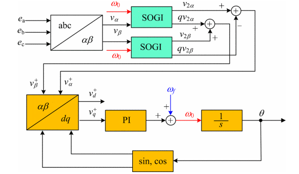
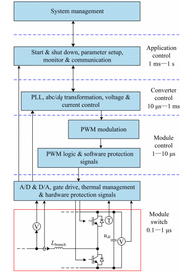
For a PET operated with a grid voltage disturbance, observability and controllability are essential. The accurate and fast detection of the frequency and phase angle of the grid voltage is essential to ensure the correct generation of reference signals and to cope with the utility codes, especially for those operated under common utility distortions such as harmonics, voltage sags, frequency variations, and phase jumps [21]. The dynamic change in the grid voltage should be considered for fast control concerns. Therefore, two key strategies for the PET have been investigated and are separately presented in this section, including the phase-locked loop (PLL) design methods, control principles, and small-signal model of the three-phase PWM rectifier. The stability issues related to the grid-connected three-phase PET are also discussed.
4.Conclusion.
A novel PET for a distribution grid called a flexible power distribution unit is proposed in this paper. DC/DC isolation for the three-phase inverters is implemented through one compact multiwinding transformer, which reduces the system complexity.Focusing on the grid code issues of the PET, such as the voltage-disturbance ride through and harmonic resonance, which have not been previously encountered, this manuscript presents the key PLL design methods under distorted grid conditions, the control principles, a small-signal model, and the input admittance of the three-phase PWM rectifier in detail. This helps understand the harmonic resonance in power-electronics-based power systems using a PET.
Source: IEEE Xplore
Statement: Respect the original, good articles worth sharing, if there is infringement please contact delete.
IEEE (pronounced "I-triple-E") stands for the Institute of Electrical and Electronics Engineers, a global professional organization dedicated to advancing technological innovation for the benefit of humanity. Founded in 1963 through the merger of the American Institute of Electrical Engineers (AIEE) and the Institute of Radio Engineers (IRE), IEEE has grown into the world’s largest technical professional society, with over 400,000 members across 160+ countries.

