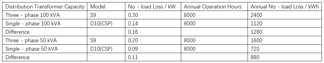
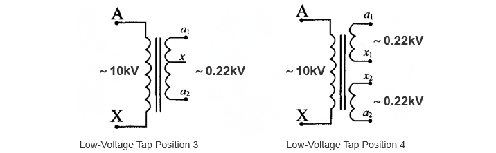
What are the technical features and applications of single-phase distribution transformers?

Echo
06/17/2025
As an expert in the application and trends of electrical equipment, I have a profound mastery of knowledge in circuits, power electronics, etc. I possess a comprehensive set of abilities including equipment design, fault diagnosis, and project management. I can precisely grasp the industry's pulse and lead the development of the electrical field.
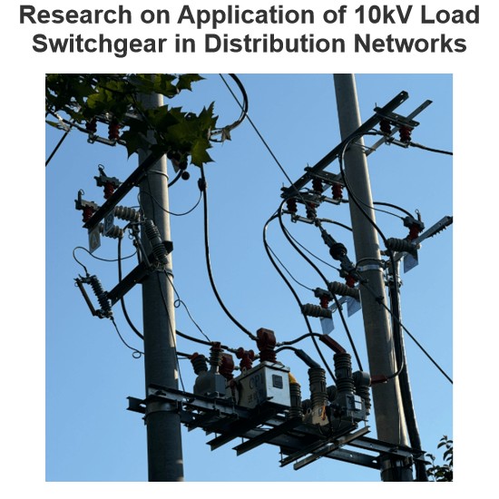
Research on Application of 10kV Load Switchgear in Distribution Networks
As a frontline worker in power distribution operation and maintenance, I deal with load switches daily—they’re the “gatekeepers” of medium - voltage distribution systems, ensuring stable power supply for users. With rapid economic development, the demand for power system safety and reliability keeps rising. Medium - voltage distribution systems are crucial for grid stability, and load switches (as key line - mounted equipment) play a pivotal role. Their main functions inc
Echo
06/28/2025
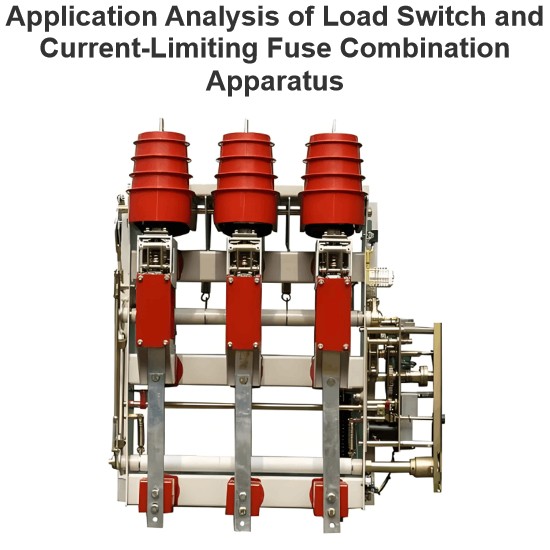
Application Analysis of Load Switch and Current-Limiting Fuse Combination Apparatus
As a front - line technician in loop - network power supply and prefabricated substation operation and maintenance, I deeply understand equipment iteration driven by high - voltage urban expansion. Per theNational Power Supply and Consumption Regulations, for equipment over 250kW or 160kVA transmission capacity, 10(6)kV high - voltage power supply and 220/380V step - down form a necessary pattern, making loop - network units and prefabricated substations key in distribution networks.I. Equipment
Echo
06/27/2025
What are the future development trends and improvement directions for household energy storage systems?
Future Development Trends and Improvement DirectionsAs a front-line technician specializing in household energy storage system maintenance, I deeply recognize that the industry is advancing toward higher efficiency and reliability. With technological iteration and standard improvement, system failure rates are expected to significantly decline, with the following four directions serving as key breakthroughs.Intelligent Diagnosis and Predictive Maintenancewill redefine fault management. By deeply
Echo
06/26/2025
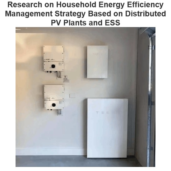
Research on Household Energy Efficiency Management Strategy Based on Distributed PV Plants and ESS
1 ZigBee - Based Smart Home SystemWith the continuous development of computer technology and information control technology, intelligent homes have evolved rapidly. Smart homes not only retain traditional residential functions but also enable users to manage household devices conveniently. Even outside the home, users can remotely monitor the internal status, facilitating home energy efficiency management and significantly enhancing quality of life.This paper designs a ZigBee - based smart home
Echo
06/26/2025


