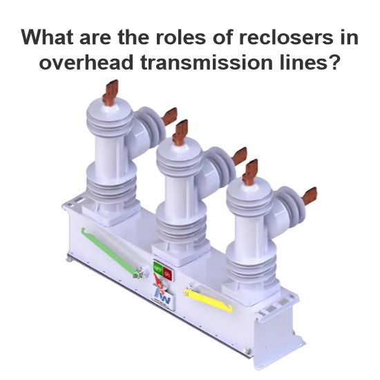
AC High - Voltage Automatic Recloser (Recloser for Short in This Article)
The AC high - voltage automatic recloser (referred to as the recloser for short in this article) is a high - voltage switchgear with self - control (it has the functions of fault current detection, operation sequence control and execution by itself, without the need for additional relay protection and operation devices) and protection functions. It can automatically detect the current and voltage passing through the main circuit of the recloser. In case of a fault, it will automatically disconnect the fault current according to the inverse - time limit protection, and automatically carry out multiple reclosing operations in accordance with the preset time sequence.
1. Main Characteristics of Recloser Scheme for Realizing Feeder Automation
The adoption of the recloser scheme for the automation of overhead distribution lines makes use of the characteristics of the recloser, such as the ability to interrupt short - circuit current, and having multiple functions including protection, monitoring and communication. It does not rely on the action of the protection switch device of the substation. Through the coordination of the protection setting values and time among reclosers, faults can be automatically located and isolated, and it has the function of extending the bus of the substation to the line.
As a protection device, the recloser on the main line can quickly section the fault and isolate the fault of the branch line.The main function of the recloser scheme is to realize feeder automation. When there is no communication automation system, it can automatically isolate faults. This enables the entire automation project to be implemented in steps. When conditions are met, the communication and automation systems can be improved, that is, all automation functions can be realized.
The feeder automation of the recloser scheme is suitable for the power supply structure of double - power hand - in - hand loop network with a relatively simple network structure. Two lines are connected through the intermediate tie - switch device. In normal operation, the tie - switch device is in the open state, and the system operates in an open - loop mode; when a fault occurs in a certain section, the normal power supply can be transferred through the network structure, making the non - fault section operate normally, thus greatly improving the power supply reliability. When the distance between the two power supplies does not exceed 10 km, considering the factors of both the number of sections and the coordination of automation, it is advisable to consider the four - section mode with three switches (reclosers), and the average length of each section is about 2.5 km.

Taking the wiring shown in Figure 1 as an example, B1 and B2 are the outgoing switches (circuit breakers) of the substation, and R0 - R2 are the line sectioning switches (reclosers). In the normal state, B1, B2, R1, and R2 are closed, and R0 is open.
-
Section ① Fault
- For a transient fault, it is restored by one or two reclosing operations of B1.
- When a permanent fault occurs: After B1 performs a reclosing operation and its opening is locked, R1 detects the loss of power in Section ①. After the power - loss duration t1), R1 opens. R0 detects the power - loss duration t2 (t2 > t1) in Section ② and then automatically closes successfully, isolating the fault in Section ①.
-
Section ② Fault
- A transient fault is restored by the reclosing operation of R1 (through the coordination of protection settings to avoid the opening of B1).
- When a permanent fault occurs: After R1 performs a reclosing operation and its opening is locked, R0 detects the power - loss duration t2 in Section ② and then automatically closes. After closing onto the faulty line, its opening is locked, isolating the fault in Section ②.
The process of fault isolation and power restoration for the two - section lines on the other side of the interconnection is the same as above.
Notes for Application (1) To realize fault isolation using the recloser scheme, the outgoing switch of the substation needs to have the zero - second quick - break function and fault time - limited quick - break function. (2) When a transient or permanent fault occurs on a branch line, the protection action of the feeder recloser installed on the branch line is used for isolation. The protection action setting value and action time of the branch recloser should be smaller than those of the main - line recloser.
The distribution network automation using the local control method can achieve the goal of improving power supply reliability with relatively low investment. Moreover, devices such as reclosers, which are of microcomputer - based and intelligent types, also provide interfaces for the future remote monitoring expansion of the system. When conditions are met, after improving the communication and master station systems, it can be transformed into a feeder automation scheme under the master station control mode.
2. How to Improve Power Supply Reliability and Reduce Line Outage Time
(1) Select a high - performance PLC (Programmable Logic Controller) as the control center of the recloser.
(2) Quickly clear transient faults to reduce outage time. In the power system, more than 70% of line faults are transient faults. If transient faults are treated the same as permanent faults, it will cause a relatively long - term outage. Therefore, a first - time quick reclosing function is added to the recloser, which can clear transient faults within 0.3 - 1.0 s (different settings for different lines), greatly reducing the outage time during transient faults.
(3) Complete the locking of both ends of the faulty section simultaneously. When a line fault occurs, a traditional circuit breaker can only lock one end of the faulty line at a time. However, using a recloser can isolate both ends of the faulty section simultaneously when a permanent line fault occurs, avoiding the outage of non - faulty sections, shortening the time to restore normal power supply, and reducing the reclosing times of the recloser, as well as the impact on the power grid system.
3. Application Principles of Reclosers in Distribution Networks
(1) Operating Conditions All faults should be given the opportunity to be treated as transient faults. Avoid the impact of inrush currents, and the opening - and - locking operation after opening should only occur in the case of permanent faults.
(2) Arrange and select reclosers economically and reasonably according to the load size and line length.
(3) Determine the rated current, breaking capacity, short - circuit current, and dynamic and thermal stable currents of the recloser according to the installation location. The upper limit of the short - circuit current should generally be selected to be above 16 kA to meet the requirement of the continuously increasing power grid capacity.
(4) Correctly set its protection coordination, such as tripping current, reclosing times, and delay time characteristics.
(5) For the coordination between reclosers, the setting of the fault current action times should be fewer level by level. The setting of the recloser delay time should be longer level by level (generally set to 8 s).