What is the difference between connecting two sources in series and parallel for DC and AC circuits?

In electrical engineering, the way power sources are connected is crucial for the behavior of a circuit. Power sources can be connected in series or in parallel, and each method is suitable for different applications. Below are the distinctions between series and parallel connections for both direct current (DC) and alternating current (AC) circuits.
Direct Current (DC) Sources
Series Connection (Series Connection)
Voltage Summation (Voltage Summation): When two or more DC sources are connected in series, the positive terminal of one source is connected to the negative terminal of the next source. Thus, the total output voltage is the sum of the voltages of each individual source. For example, if two 12-volt batteries are connected in series, the total output voltage would be 24 volts.
Equal Current (Equal Current): Ideally, the current through the entire circuit is the same, regardless of the number of sources connected in series. However, it is important to note that all the series-connected sources should have matching current capacities to avoid overload or damage.
Parallel Connection (Parallel Connection)
Equal Voltage (Equal Voltage): When two or more DC sources are connected in parallel, all the positive terminals are connected together, and all the negative terminals are connected together. Thus, the total output voltage is equal to the voltage of a single source. For example, if two 12-volt batteries are connected in parallel, the total output voltage remains 12 volts.
Current Addition (Current Addition): In a parallel connection, the total current capacity is the sum of the current capacities of each individual source. For instance, if two identical 12-volt, 5-amp-hour batteries are connected in parallel, the total current capacity would be 10 amp-hours. Parallel connections can be used to increase the system's current output or provide redundancy.
Alternating Current (AC) Sources
Series Connection (Series Connection)
Voltage Addition (Voltage Addition): Similar to DC sources, AC sources add their voltages when connected in series. However, AC voltages are measured based on peak or RMS values, so phase differences must be considered. If two AC sources are in phase, their voltages simply add up. If they are out of phase (by 180 degrees), the voltages might cancel each other out.
Current Relationship (Current Relationship): In a series circuit, the current is the same through each component. However, it is important to note that the impedance (including resistance, inductance, and capacitance) of AC sources affects the current.
Parallel Connection (Parallel Connection)
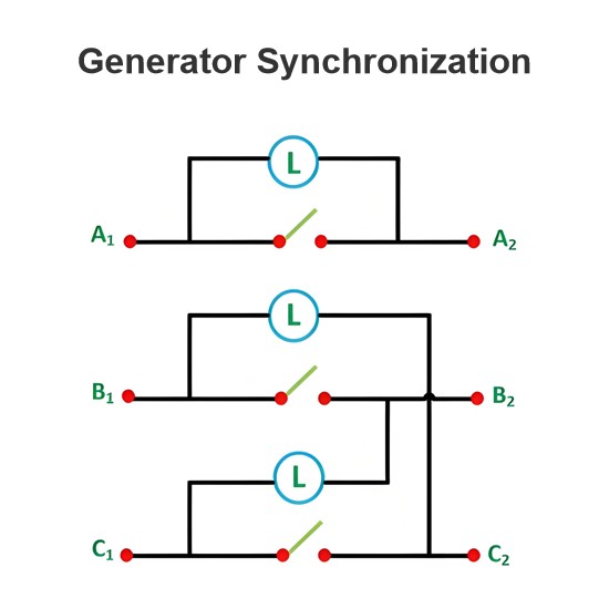
Equal Voltage (Equal Voltage): When AC sources are connected in parallel, their output voltages are equal. Parallel connections are mainly used for synchronous generators or other power sources to increase the total available power or provide redundancy.
Current Addition (Current Addition): In a parallel connection, the total current is the vector sum of the currents of each individual source. This requires consideration of the phase difference between the sources, as phase differences affect the total current. If AC sources are synchronized and in phase, their currents can simply be added.
Summary
For DC Sources
Series Connection: Increases the total voltage.
Parallel Connection: Increases the total current capacity.
For AC Sources
Series Connection: Increases the total voltage (depending on phase relationship).
Parallel Connection: Increases the total available power (requires synchronization and consideration of phase difference).
In practical applications, whether dealing with DC or AC sources, it is essential to understand the impact of the connection method on the circuit and ensure that the circuit design complies with safety standards and meets the desired performance requirements.
The Electricity Encyclopedia is dedicated to accelerating the dissemination and application of electricity knowledge and adding impetus to the development and innovation of the electricity industry.