What is Short Transmission Line?
Short Transmission Line Definition
A short transmission line is defined as a transmission line less than 80 km (50 miles) long or with a voltage less than 69 kV.
A short transmission line is defined as a transmission line with an effective length less than 80 km (50 miles), or with a voltage less than 69 kV. Unlike medium transmission lines and long transmission lines, the line charging current is negligible, and hence the shunt capacitance can be ignored.
For short length, the shunt capacitance of this type of line is neglected and other parameters like electrical resistance and inductor of these short lines are lumped, hence the equivalent circuit is represented as given below. Let’s draw the vector diagram for this equivalent circuit, taking receiving end current Ir as reference. The sending end and receiving end voltages make angle with that reference receiving end current, of φs and φr, respectively.
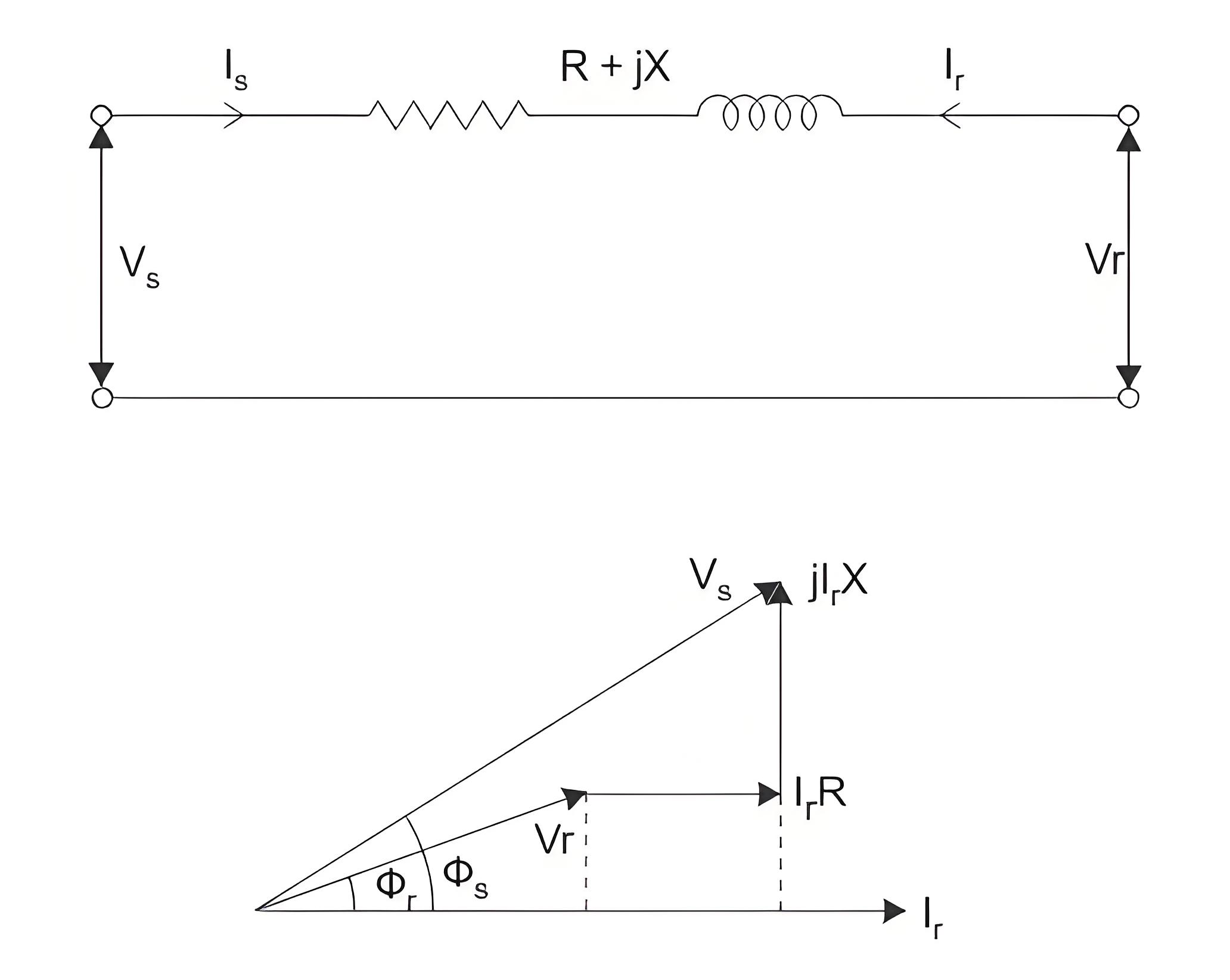
Since the shunt capacitance is neglected, the sending end current is the same as the receiving end current.

We can see from the short transmission line phasor diagram above that Vs is approximately equal to:


As there is no capacitance, during no-load condition the current through the line is considered as zero, hence at no load condition, receiving end voltage is the same as sending end voltage.
As per dentition of voltage regulation of power transmission line,
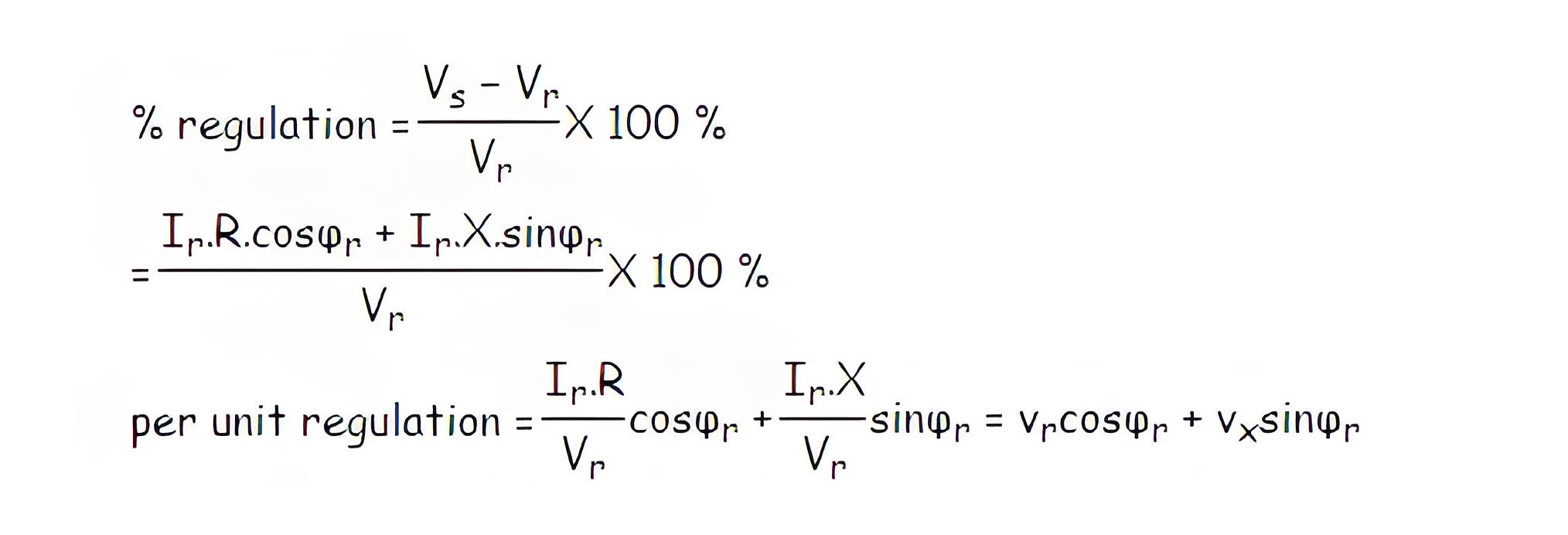
Here, Vr and Vx are the per unit resistance and reactance of the short transmission line respectively.
An electrical network usually has two input and two output terminals, forming a two-port network. This model simplifies network analysis and can be solved using a 2×2 matrix.
A transmission as it is also an electrical network, and hence the transmission line can be represented as a two-port network.
The two-port network of a transmission line is represented by a 2×2 matrix using ABCD parameters, which describe the relationship between voltages and currents in the network.

Where, A, B, C and D are the different constants of the transmission network.
If we put Ir = 0 at equation (1), we get,

Hence A is the voltage impressed at the sending end per volt at the receiving end when receiving end is open. It is dimensionless. If we put Vr = 0 at equation (1), we get

C is the current in amperes into the sending end per volt on open circuited receiving end. It has the dimension of admittance.
D is the current in amperes into the sending end per amp on the short-circuited receiving end. It is dimensionless.
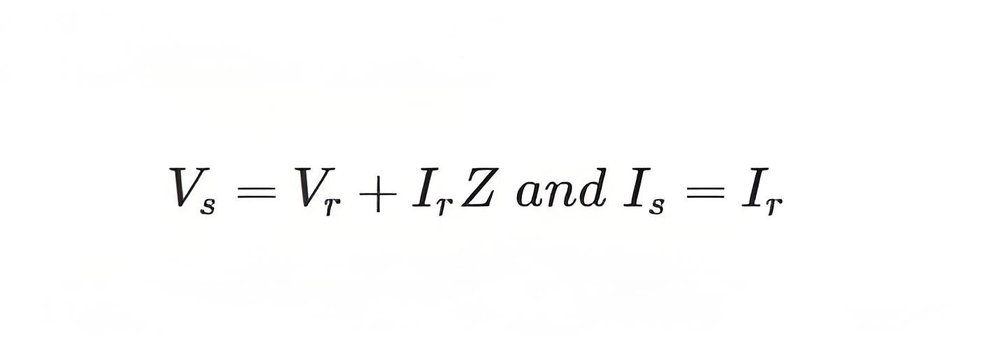
Now from the equivalent circuit, it is found that,

Comparing these equations with equation 1 and 2 we get, A = 1, B = Z, C = 0 and D = 1. As we know that the constant A, B, C, and D are mathematically related to a passive network as:
AD − BC = 1
Here, A = 1, B = Z, C = 0, and D = 1
⇒ 1.1 − Z.0 = 1
So the values calculated are correct for a short transmission line. From the above equation (1),
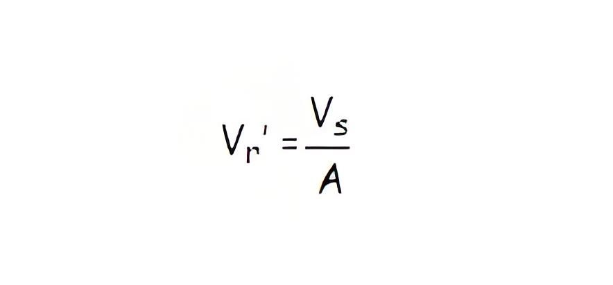
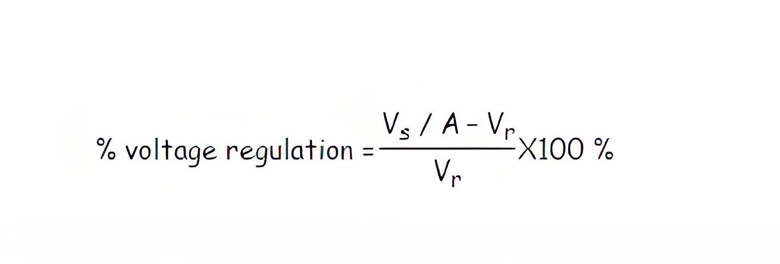
When Ir = 0 that means receiving end terminals is open circuited and then from equation 1, we get receiving end voltage at no load.
and as per definition of voltage regulation of power transmission line,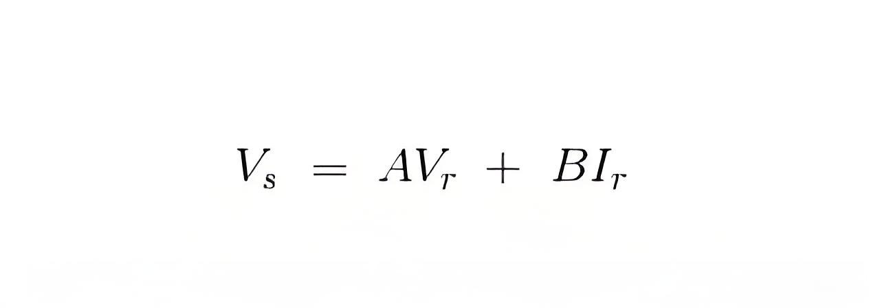
Negligible Shunt Capacitance
In a short transmission line, the shunt capacitance is ignored, simplifying calculations.
Phasor Diagram
The phasor diagram uses the receiving end current as a reference for comparing voltages.
Two-Port Network Representation
Short transmission lines can be modeled as two-port networks, using ABCD parameters for analysis.
Performance Efficiency
The efficiency of a short transmission line is calculated similarly to other electrical devices, based on its electrical resistance.

The Electricity Encyclopedia is dedicated to accelerating the dissemination and application of electricity knowledge and adding impetus to the development and innovation of the electricity industry.

