High Voltage Direct Current Transmission
HVDC Transmission Definition
HVDC transmission is the method of transmitting electricity in DC form over long distances using either submarine cables or overhead lines.
Conversion and Components
The hvdc transmission system uses rectifiers and inverters for converting AC to DC and vice versa, with components like smoothing reactors and harmonic filters to ensure stability and reduce interference.
HVDC Transmission System
We know that AC power is generated in the generating station. This should first be converted into DC. The conversion is done with the help of rectifier. The DC power will flow through the overhead lines. At the user end, this DC has to be converted into AC. For that purpose, an inverter is placed at the receiving end.
Thus, there will be a rectifier terminal in one end of HVDC substation and an inverter terminal in the other end. The power of the sending end and user end will be always equal (Input Power = Output Power).
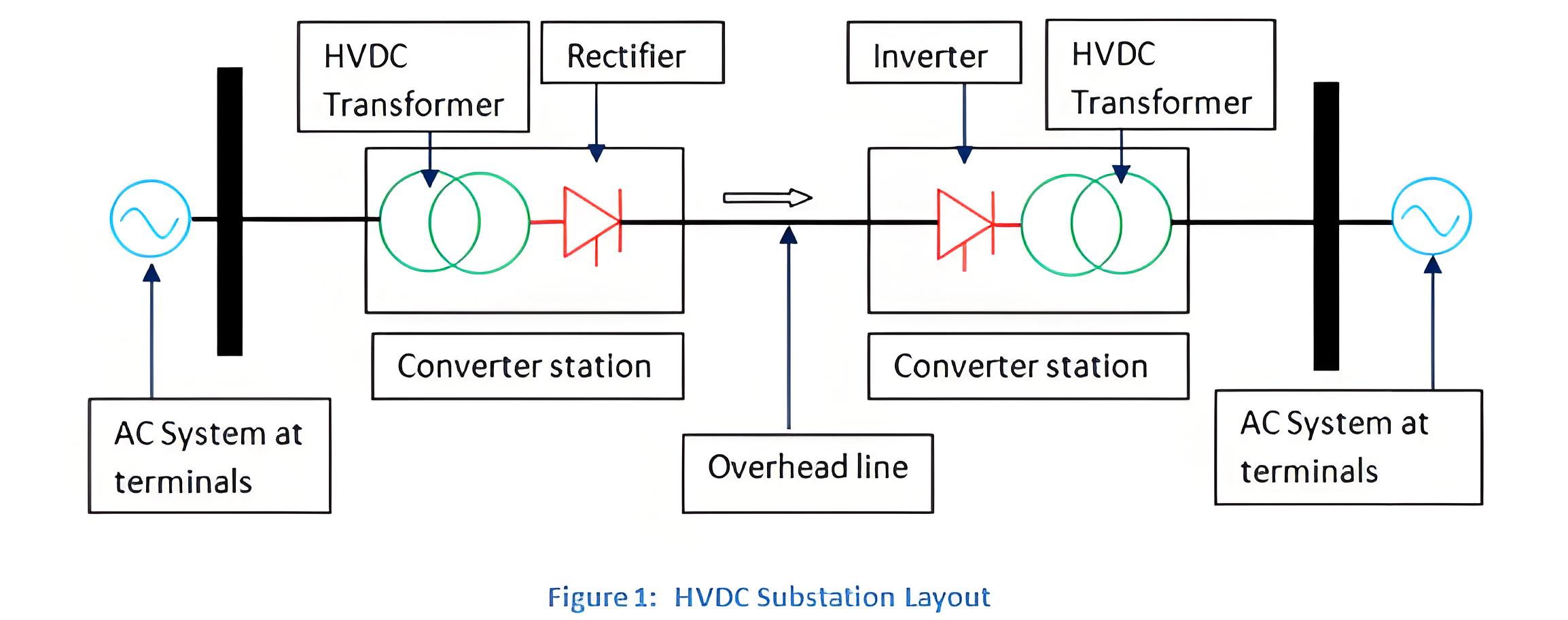
When there are two converter stations at both ends and a single transmission line is termed as two terminal DC systems. When there are two or more converter stations and DC transmission lines is termed as multi-terminal DC substation.
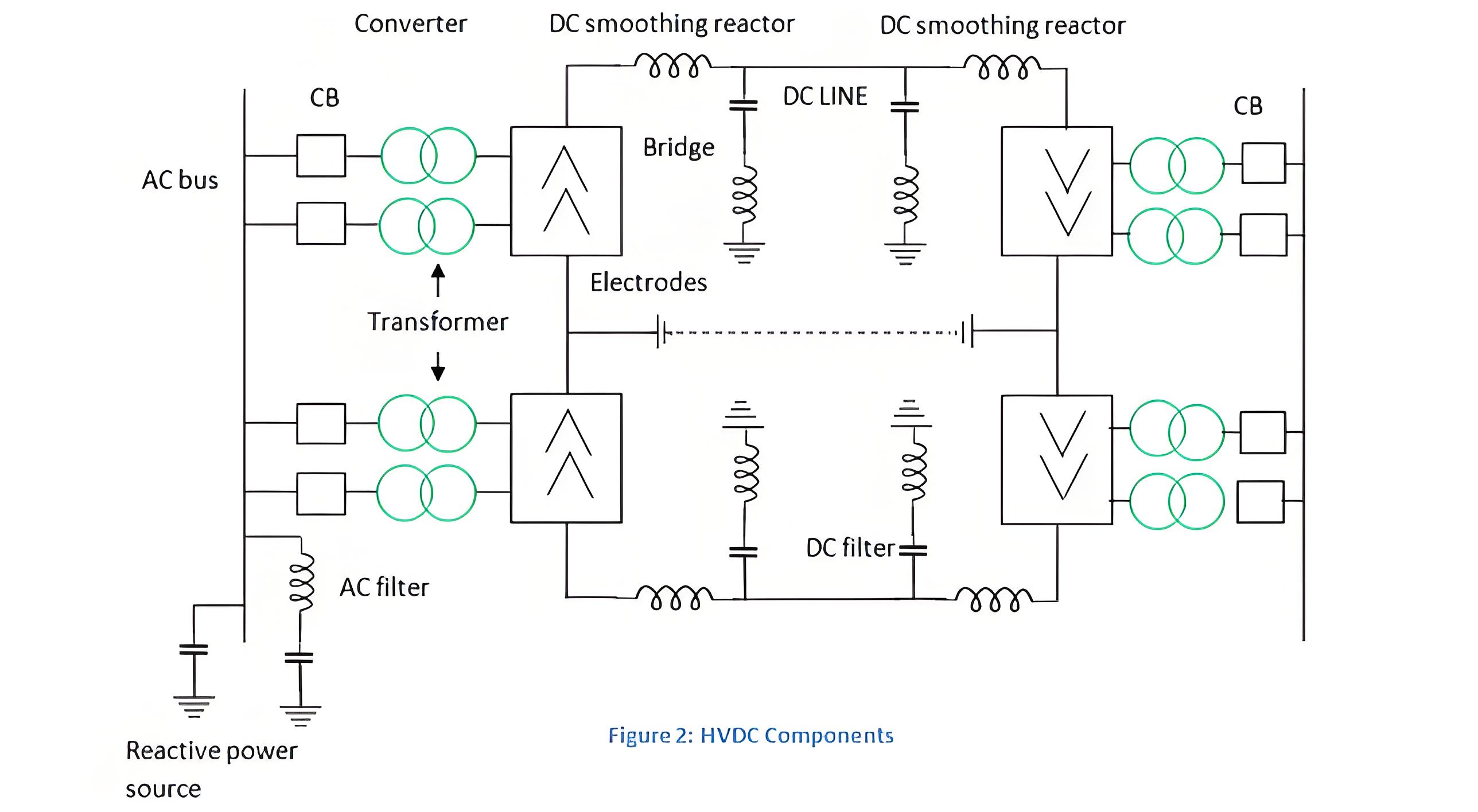
The components of the HVDC Transmission system and its function are explained below.
Converters: The AC to DC and DC to AC conversion are done by the converters. It includes transformers and valve bridges.
Smoothing Reactors: Each pole consist of smoothing reactors which are of inductors connected in series with the pole. It is used to avoid commutation failures occurring in inverters, reduces harmonics and avoids discontinuation of current for loads.
Electrodes: They are actually conductors which are used to connect the system to the earth.
Harmonic Filters: It is used to minimize the harmonics in voltage and current of the converters used.
DC Lines: It can be cables or overhead lines.
Reactive Power Supplies: The reactive power used by the converters could be more than 50% of the total transferred active power. So the shunt capacitors provide this reactive power.
AC Circuit Breakers: The fault in the transformer is cleared by the circuit breakers. It also used to disconnect the DC link.
Link Types
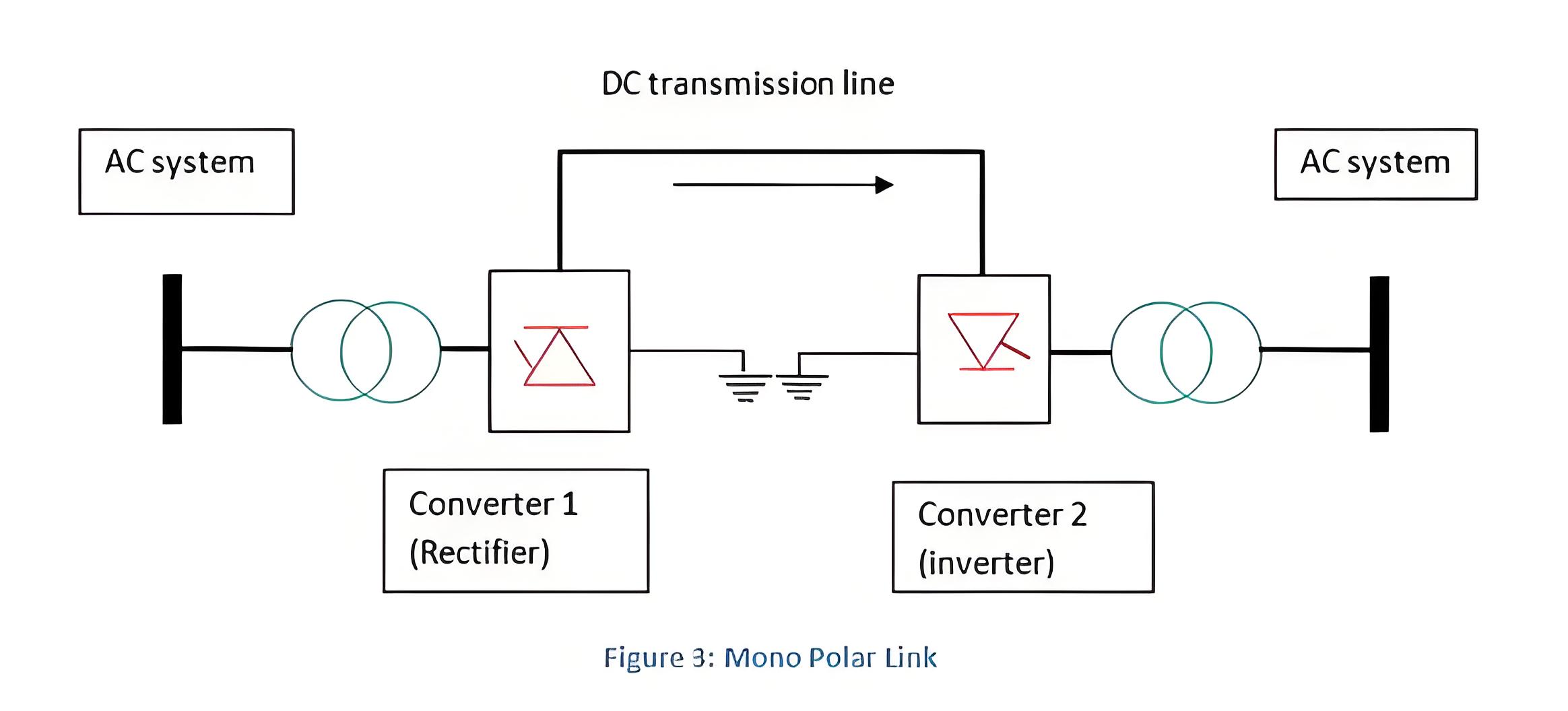
Mono-polar Link
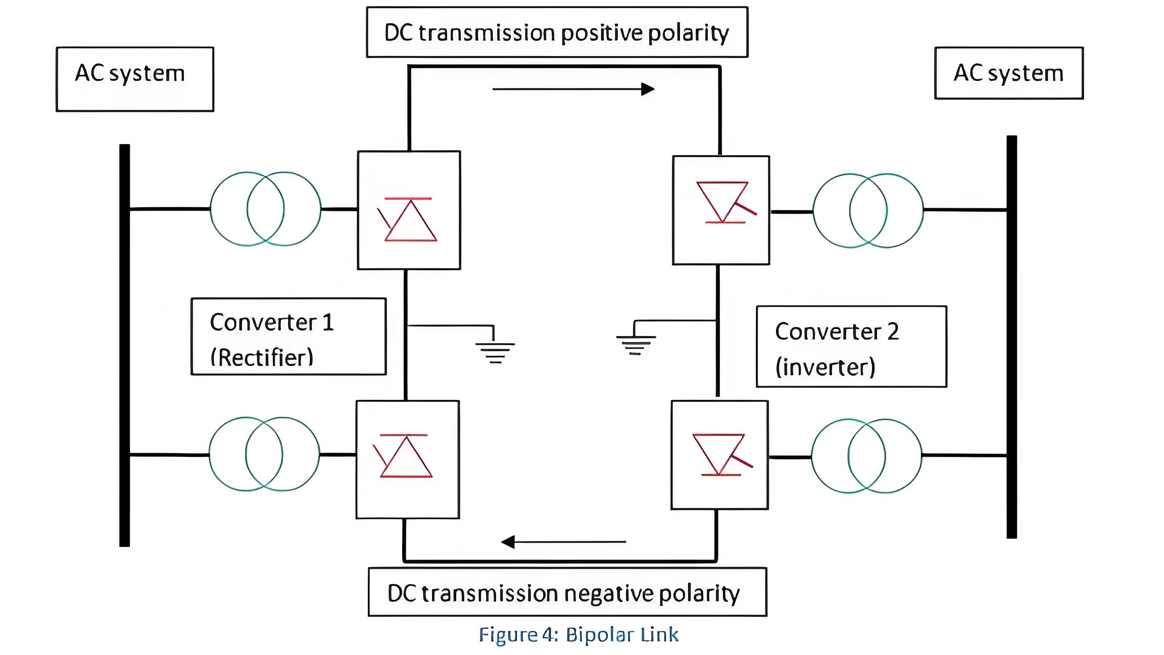
Bipolar Link
Homopolar Link
Single conductor is required and water or ground act as the return path. If the earth resistivity is high, metallic return is used.
Double converters of same voltage rating are used in each terminal. The converter junctions are grounded.
It consists of more than two conductors which is having equal polarity generally negative. Ground is the return path.
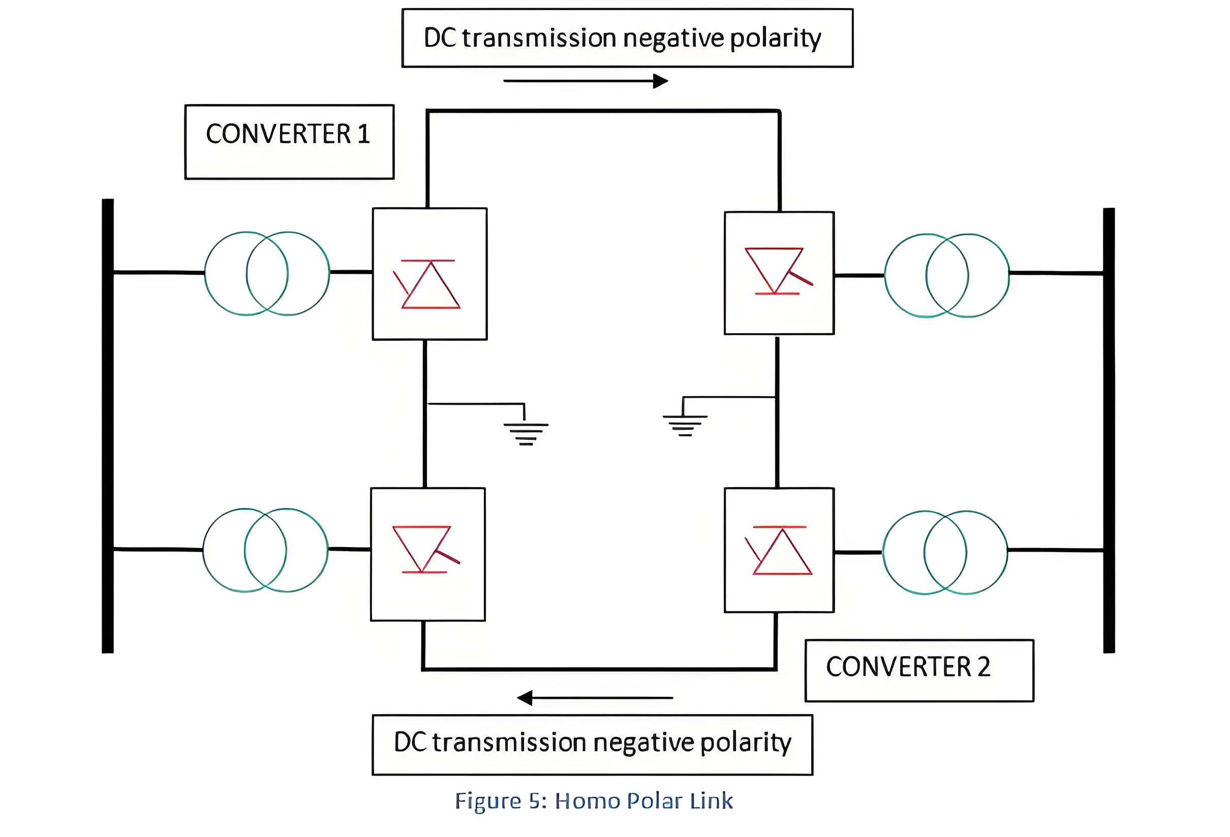
Multi Terminal Links
It is used to connect more than two points and is rarely used.
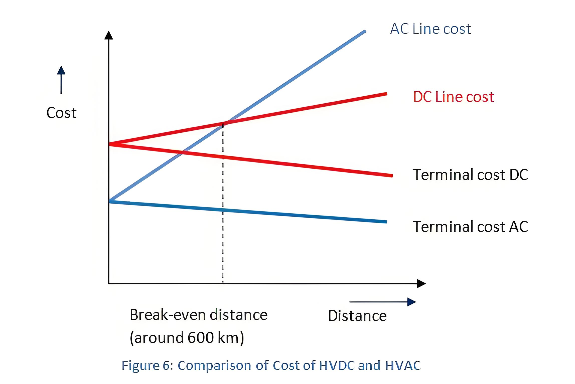
Comparison of both HVAC and HVDC Transmission System
Efficiency Advantages
Converters with small overload capacity are used.
Circuit Breakers, Converters and AC filters are expensive especially for small distance transmission.
No transformers for altering the voltage level.
HVDC link is extremely complicated.
Uncontrollable power flow.
Practical Applications
Undersea and underground cables
AC network interconnections
Interconnecting Asynchronous system
The Electricity Encyclopedia is dedicated to accelerating the dissemination and application of electricity knowledge and adding impetus to the development and innovation of the electricity industry.

