Electrical Bus System
Electrical Bus System Definition
An electrical bus system is a setup of electrical conductors that allows for efficient power distribution and management within a substation.
Single Bus System
A single bus system is simple and cost-effective but requires power interruption for maintenance.
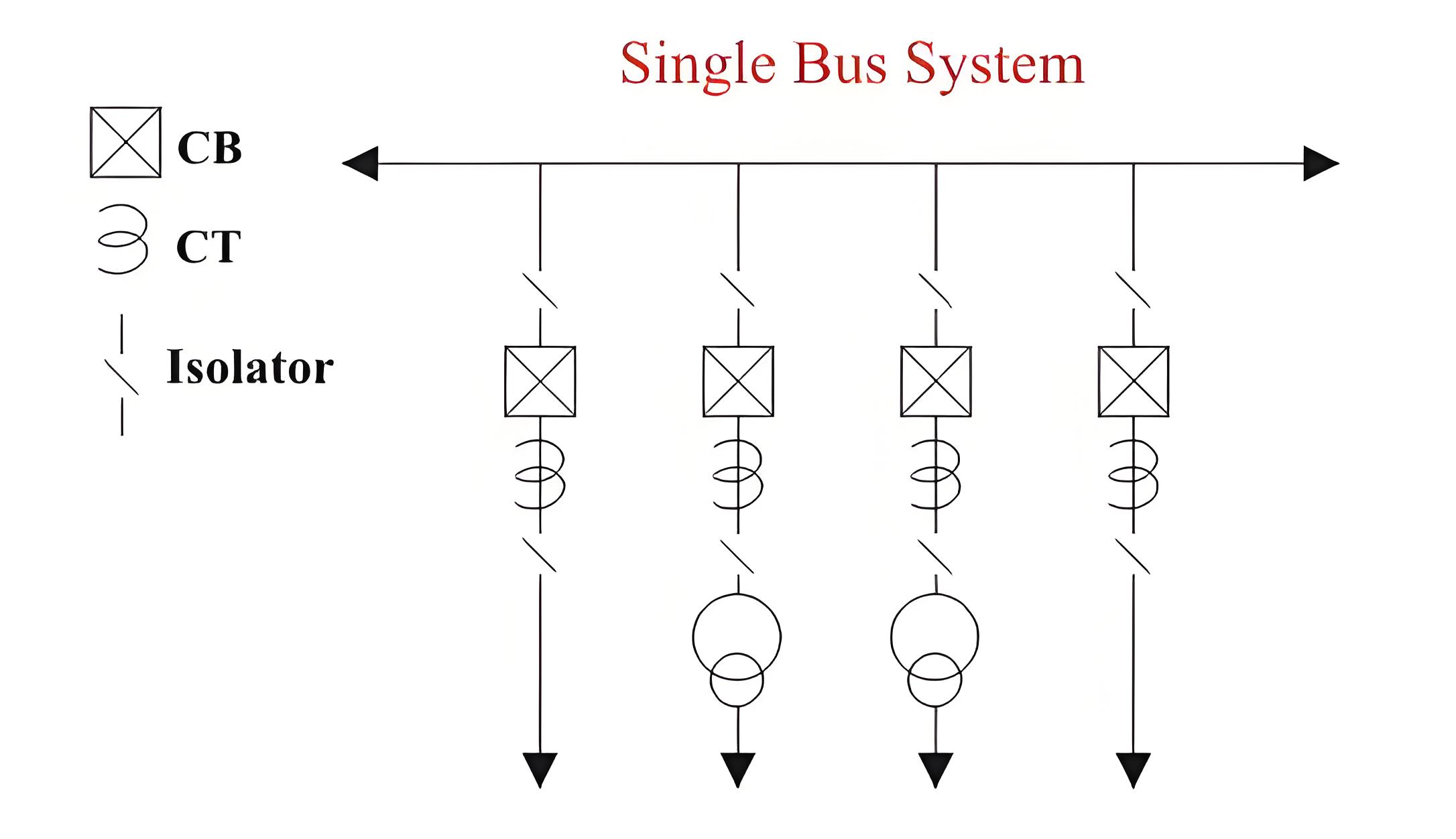
Advantages of Single Bus System
This is very simple in design.
This is very cost effective scheme.
This is very convenient to operate.
Disadvantages of Single Bus System
A major issue with this arrangement is that maintenance on any bay requires interrupting the connected feeder or transformer.
The indoor 11 KV switch boards have quite often single bus bar arrangement.
Single Bus System with Bus Sectionalizer
Some advantages are realized if a single bus bar is sectionalized with circuit breaker. If there are more than one incoming and the incoming sources and outgoing feeders are evenly distributed on the sections as shown in the figure, interruption of a system can be reduced to a reasonable extent.
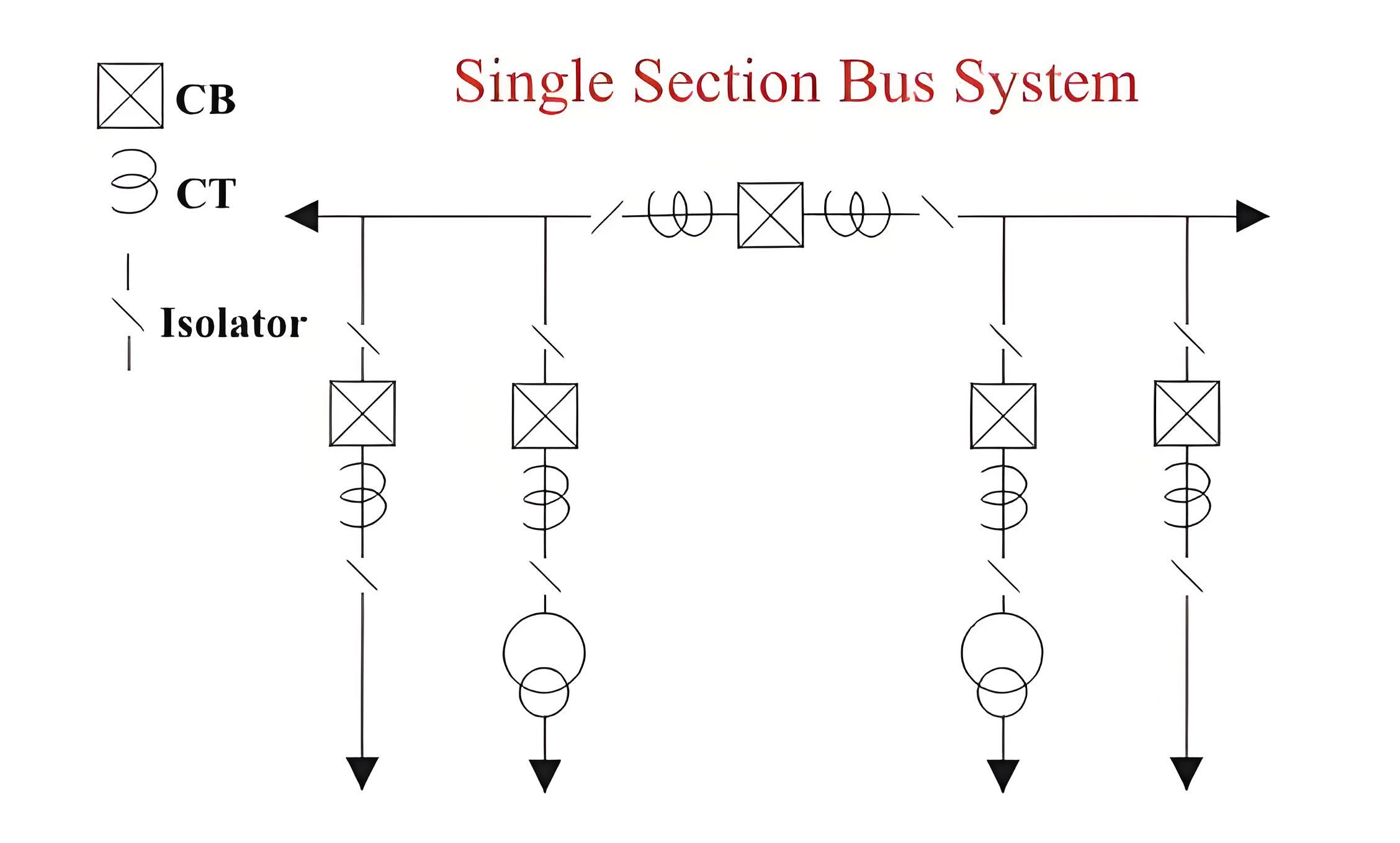
Advantages of Single Bus System with Bus Sectionalizer
If any of the sources is out of the system, still all loads can be fed by switching on the sectional circuit breaker or bus coupler breaker. If one section of the bus bar system is under maintenance, a part load of the substation can be fed by energizing the other section of the bus bar.
Disadvantages of Single Bus System with Bus Sectionalizer
As in the case of a single bus system, maintenance of equipment of any bay cannot be possible without interrupting the feeder or transformer connected to that bay.
The use of isolator for bus sectionalizing does not fulfill the purpose. The isolators have to be operated ‘off circuit’ and which is not possible without total interruption of bus-bar. So investment for bus-coupler breaker is required.
Double Bus System
In double bus bar system two identical bus bars are used in such a way that any outgoing or incoming feeder can be taken from any of the bus.
Actually every feeder is connected to both of the buses in parallel through individual isolator as shown in the figure. By closing any of the isolators, one can put the feeder to the associated bus. Both of the buses are energized, and total feeders are divided into two groups, one group is fed from one bus and other from other buses. But any feeder at any time can be transferred from one bus to other. There is one bus coupler breaker which should be kept close during bus transfer operation. For transfer operation, one should first close the bus coupler circuit breaker then close the isolator associated with the bus to where the feeder would be transferred and then open the isolator associated with the bus from where the feeder is transferred. Lastly, after this transfer operation, he or she should open the bus coupler breaker.
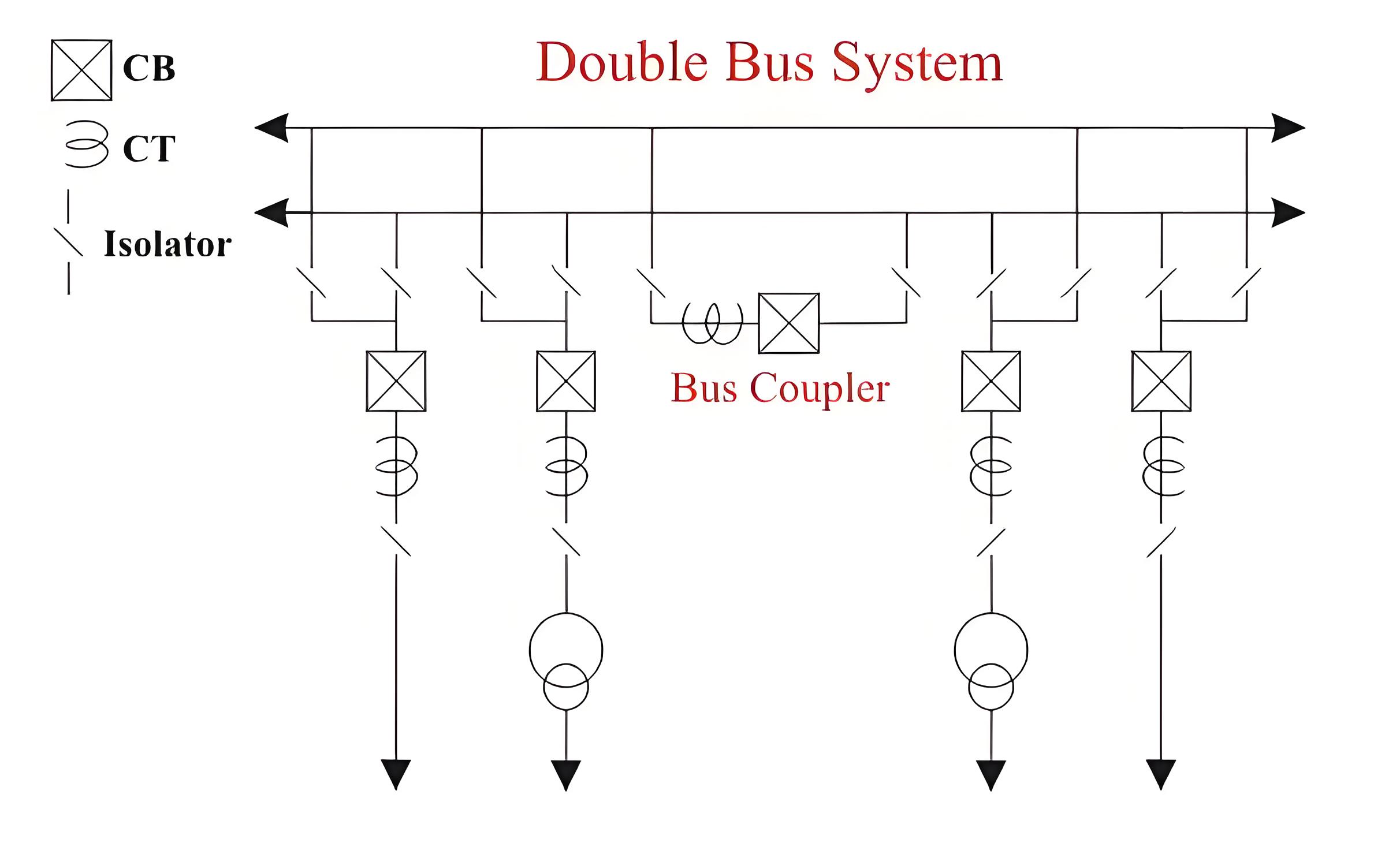
Advantages of Double Bus System
Double Bus Bar Arrangement increases the flexibility of system.
Disadvantages of Double Bus System
The arrangement does not permit breaker maintenance without interruption.
Double Breaker Bus System
In double breaker bus bar system two identical bus bars are used in such a way that any outgoing or incoming feeder can be taken from any of the bus similar to double bus bar system. The only difference is that here every feeder is connected to both of the buses in parallel through individual breaker instead only isolator as shown in the figure.
By closing any of the breakers and its associated isolators one can put the feeder to respective bus. Both of the buses are energized, and total feeders are divided into two groups, one group is fed from one bus and other from other buses similar to the previous case. But any feeder at any time can be transferred from one bus to other. There is no need for bus coupler as because the operation is done by breakers instead of isolators.
For transfer operation, one should first close the isolators and then the breaker associated with the bus to where the feeder would be transferred, and then he or she opens the breaker and then isolators associated with the bus from where the feeder is transferred.
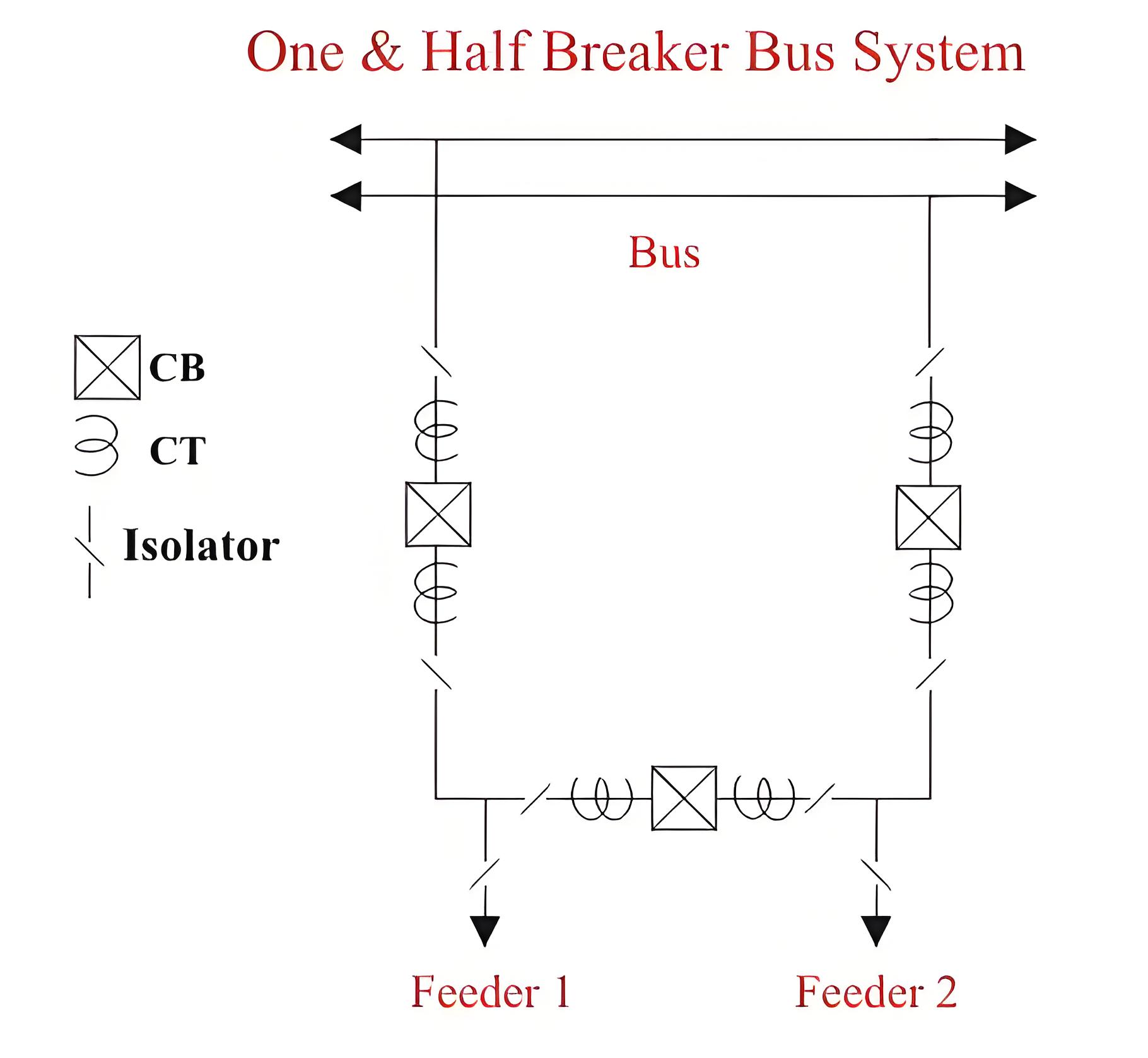
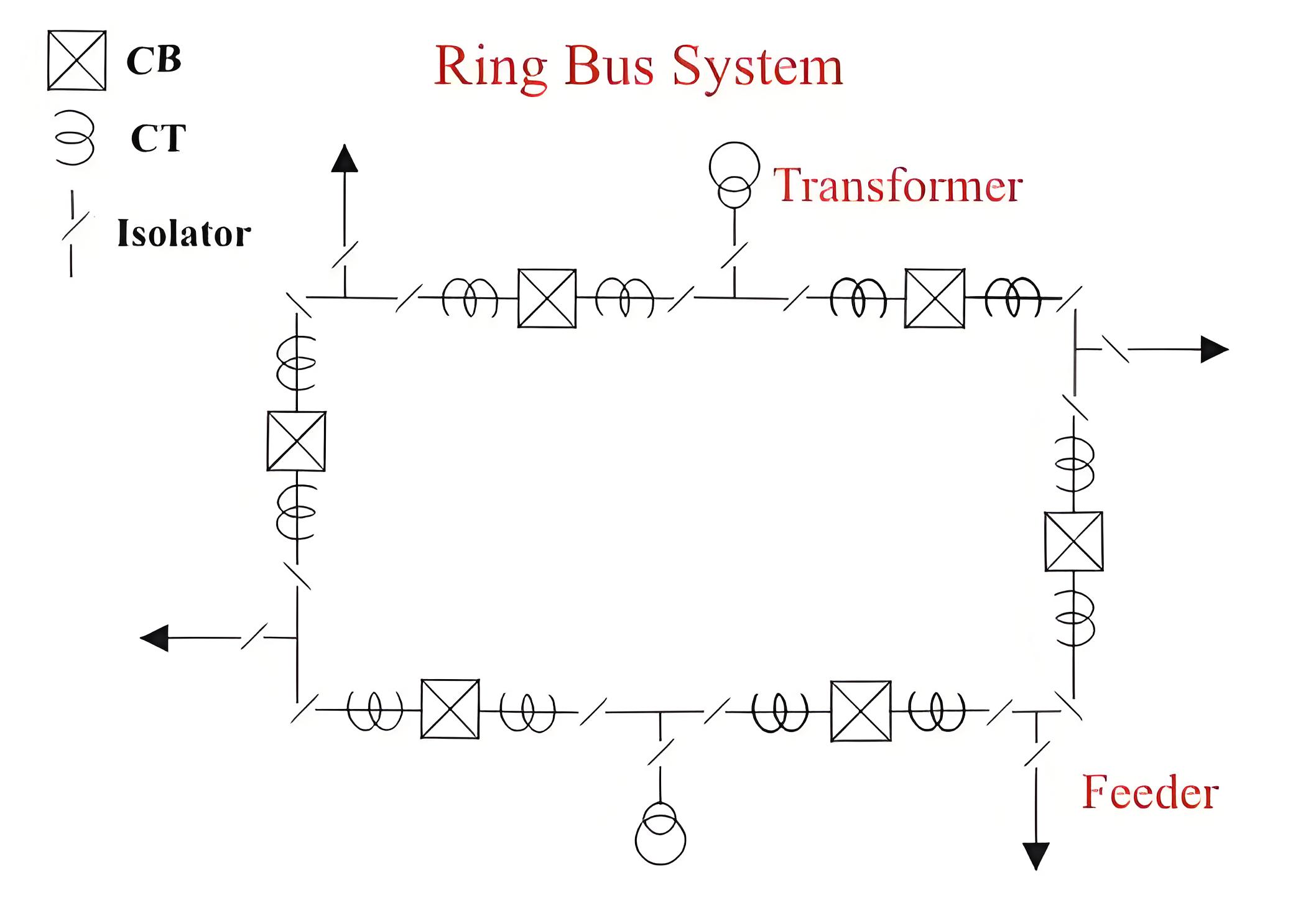
Ring Bus System
The schematic diagram of the system is given in the figure. It provides a double feed to each feeder circuit, opening one breaker under maintenance or otherwise does not affect supply to any feeder. But this system has two major disadvantages.
One as it is a closed circuit system it is next to impossible to extend in future and hence it is unsuitable for developing systems. Secondly, during maintenance or any other reason, if any one of the circuit breaker in ring loop is switched off, the reliability of system becomes very poor as because closed loop becomes opened. Since at that moment for any tripping of any breaker in the open loop causes interruption in all the feeders between the tripped breaker and open end of the loop.
The Electricity Encyclopedia is dedicated to accelerating the dissemination and application of electricity knowledge and adding impetus to the development and innovation of the electricity industry.
