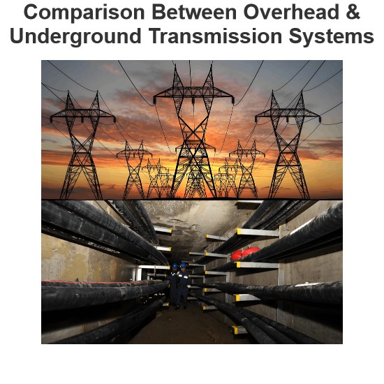
Why are Overhead Power Transmission Lines Not Insulated?

Why Aren't High - Voltage Wires Insulated?
Overhead transmission lines are commonly left uninsulated, and this practice is grounded in several compelling rationales:
Cost - Efficiency
Insulating overhead transmission lines over vast distances represents a prohibitively expensive undertaking. These lines often stretch across hundreds of miles, and covering them with conventional insulation materials would impose exorbitant financial burdens. The sheer scale of the infrastructure makes insulation not only a logistical challenge but also an economic non - starter. By forgoing insulation, power transmission and distribution companies can realize substantial cost savings, which can then be redirected towards other critical aspects of grid development and maintenance.
Weight Management
The thickness of insulation required for transmission lines is directly proportional to the voltage level. In the case of Extra High Voltage (EHV) lines, which operate at extremely high electrical potentials, the insulation would need to be correspondingly thick. This added bulk translates into a significant increase in the overall weight of the lines. Such a heavy load not only complicates the installation process but also places greater stress on the supporting structures, including poles, towers, and associated hardware. By eliminating insulation, the weight of the lines is minimized, facilitating easier installation and reducing the strain on the infrastructure.
Material and Infrastructure Simplification
For EHV lines, the necessity of thick insulation has a cascading effect on the entire transmission system. The additional weight necessitates stronger supports, more robust insulators, and sturdier foundations for poles and towers. This not only drives up the overall cost of the infrastructure but also adds complexity to the design and construction process. In contrast, bare wires offer a simpler and more straightforward solution for power transmission, achieving the same functional objectives without the need for elaborate and costly additional materials and infrastructure.
Conductivity Enhancement
As voltage levels increase, the dielectric strength of insulators diminishes. For extra - high - voltage applications, such as those operating in the range of 450 kV to 600 kV, the insulation would have to be extremely thick to maintain electrical integrity. However, this thick insulation acts as a barrier to the efficient dissipation of heat generated during power transmission. Heat buildup can lead to increased electrical resistance and reduced conductivity, ultimately resulting in power losses. Bare conductors, on the other hand, allow for unimpeded heat transfer, ensuring optimal conductivity and minimizing energy losses in the transmission process.
Maintenance Ease
Maintaining insulated lines presents a more arduous and costly challenge compared to bare lines. Insulated lines require regular, meticulous inspections to ensure that the insulation remains intact and free from damage or degradation. Even minor defects in the insulation can pose significant safety risks and disrupt power transmission. In contrast, bare conductors can be more easily visually inspected for signs of wear, damage, or other issues. This simplicity in maintenance reduces the frequency and complexity of inspections, lowering overall maintenance costs and ensuring the reliable operation of the transmission system.
Heat Dissipation
Overhead transmission lines carry substantial electrical currents, which inherently generate significant amounts of heat. Insulating these lines would impede the natural dissipation of this heat, effectively trapping it within the system. This trapped heat could lead to overheating, a condition that poses a serious threat to the reliability and longevity of the transmission infrastructure. Excessive heat can degrade conductor materials, increase electrical resistance, and even cause mechanical failures, all of which can disrupt power delivery and potentially lead to system - wide outages.
Safety
Although the conductors of overhead transmission lines are bare and lack continuous insulation, the system is engineered with robust safety features. These lines are strategically installed at considerable heights, making it extremely difficult for people, vehicles, or wildlife to come into contact with them. The ample vertical and horizontal clearances between the power lines and the surrounding environment act as a natural form of insulation, reducing the likelihood of electrical faults caused by accidental contact. This spatial separation is a crucial safeguard, minimizing the risk of electrocution and protecting both the public and the integrity of the power transmission system.
Rather than relying on continuous conductor insulation, overhead transmission lines incorporate a sophisticated design that emphasizes proper spacing between phase wires and adequate ground clearances. This design approach effectively prevents flashovers and electrical discharges, which could otherwise occur due to electrical arcing between conductors or to the ground. At specific connection points, such as where the lines attach to supporting structures, insulators, and bushings made from high - quality insulating materials are employed.
These components play a vital role in preventing electrical leakage, ensuring that the electrical current remains within the intended path and maintaining the safe and efficient operation of the entire transmission system. Through these comprehensive design considerations, overhead transmission lines are able to deliver electrical power over long distances with a high degree of safety and reliability.
The Electricity Encyclopedia is dedicated to accelerating the dissemination and application of electricity knowledge and adding impetus to the development and innovation of the electricity industry.