Differential Protection of a Generator
Generator Differential Protection
Differential protection for a generator primarily safeguards the stator windings against earth faults and phase - to - phase faults. Stator winding faults pose a significant threat, capable of inflicting severe damage on the generator. To protect the stator windings, a differential protection system is utilized to clear faults in the shortest time possible, thereby minimizing the extent of damage.
Merz - Prize Circulating Current System
In this protection scheme, the currents at the two ends of the protected section are compared. During normal operation, the magnitudes of the currents in the secondary windings of the current transformers are equal. However, when a fault occurs, a short - circuit current flows through the system, causing the current magnitudes to diverge. This difference in current under fault conditions is channeled through the relay's operating coil.
Once the current exceeds the preset threshold, the relay closes its contacts, triggering the circuit breaker to trip. This action isolates the faulty section from the rest of the system. Such a protection mechanism is known as the Merz - Prize circulating current system, which proves highly effective in detecting and responding to earth faults and phase - to - phase faults.
Connection of the Differential Protection System
The differential protection system necessitates two identical current transformers, which are installed on either side of the protected zone. The secondary terminals of these current transformers are connected in a star configuration, and their end terminals are linked via pilot wires. Meanwhile, the relay coils are connected in a delta configuration. The neutral points of the current transformers and the relay are then connected to a common terminal. This specific wiring arrangement ensures the accurate detection of current imbalances and enables prompt fault isolation.
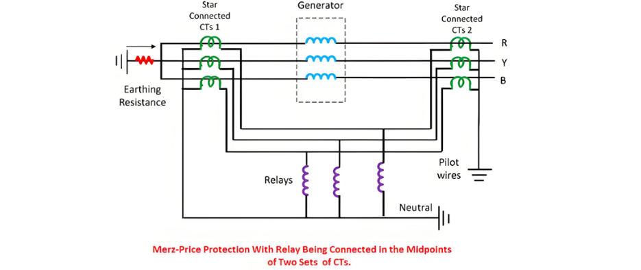
The relay is connected across the equipotential points of the three pilot wires to ensure that each current transformer bears an equal burden. Since the midpoint of each pilot wire represents its equipotential point, the relay is strategically positioned at the midpoint of these wires.
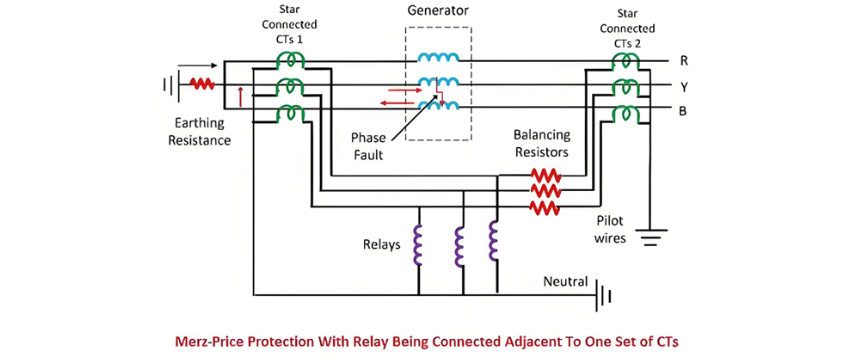
For the differential protection system to function optimally, it is crucial to place the relay coils close to the current transformers near the main circuit. This can be achieved by inserting balancing resistors in series with the pilot wires, effectively shifting the equipotential points closer to the main circuit breaker.
Working Principle of the Differential Protection System
Suppose an insulation breakdown occurs on the R phase of the network, triggering a fault. As a result, the currents in the secondaries of the current transformers become imbalanced. This imbalance generates differential currents that flow through the relay coil. Consequently, the relay activates and issues a tripping command to the circuit breaker, isolating the faulty section from the rest of the system.
However, this protection system has a significant limitation: it is highly sensitive to the magnetizing inrush current of the transformer. The inrush current can cause the relay to malfunction. To address this issue, a biased differential relay is employed. This type of relay permits a certain level of unbalanced current to pass through its coil without triggering unnecessary operation.
To further mitigate the impact of the magnetizing inrush current, a restraining coil is incorporated into the design. The restraining coil effectively reduces the influence of the inrush current, making the relay immune to false tripping caused by magnetizing inrush. Relays equipped with such a configuration are known as biased differential relays.
Fault Scenario and Relay Operation
When a fault occurs between any two phases, for example, between phases Y and B, a short - circuit current will flow through these two phases. This fault disrupts the balance of currents flowing through the current transformers (CTs). Consequently, a differential current passes through the relay's operating coil, causing the relay to trip and open its contacts, thereby isolating the faulty section from the electrical system.
Issues with the Differential Protection System
In a differential protection system, a neutral resistance wire is typically used to mitigate the adverse effects of earth fault currents. However, when an earth fault occurs close to the neutral point, a small electromotive force (emf) generates a relatively small short - circuit current that flows through the neutral. The resistance of the neutral grounding further reduces this current. As a result, only a minimal current reaches the relay. Since this small current is insufficient to activate the relay coil, the fault may go undetected, potentially leading to damage to the generator.
Modified Differential Protection System Scheme
To address the above - mentioned problem, an improved differential protection system scheme has been developed. This modified scheme incorporates two distinct elements: one designed for protecting against phase faults and the other for safeguarding against earth faults.
The phase - fault protection elements are connected in a star configuration along with a resistor. Meanwhile, the earth - fault relay is positioned between the star - connected phase elements and the neutral point. Specifically, two phase - fault elements, together with a balancing resistor, are connected in a star pattern, and the earth - fault relay is then connected between the star connection and the neutral pilot wire. This configuration enhances the system's ability to accurately detect and respond to both phase and earth faults, improving the overall reliability of the differential protection system.
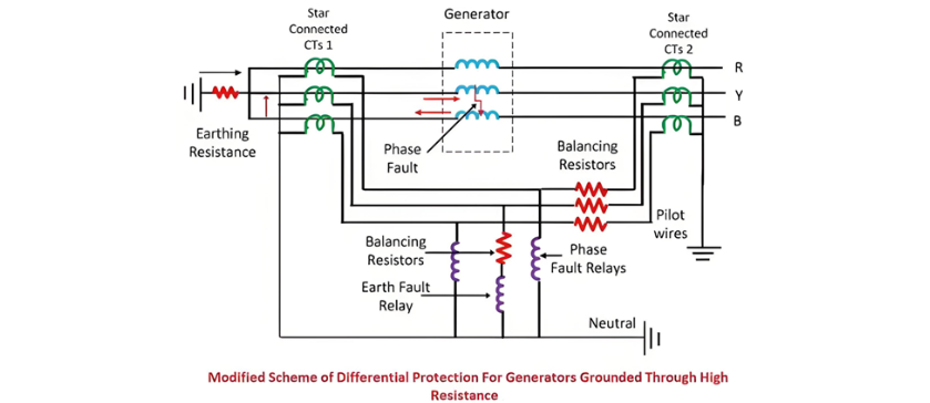
The star - connected circuit exhibits symmetry, ensuring that any balanced overflow current originating from the current - circulating point will not pass through the earth - fault relay. As a result, within this system, the sensitive earth - fault relay can operate with a high level of stability, reliably detecting earth faults without being triggered by normal balanced current fluctuations.
The Electricity Encyclopedia is dedicated to accelerating the dissemination and application of electricity knowledge and adding impetus to the development and innovation of the electricity industry.

