Earthing of Substation Equipment
Method of Earthing
We connect all the points to be earthed to the earthing grid using corrosion-resistant mild steel rods, buried at least 600 mm below ground. If these rods cross a cable trench, road, underground pipework, or rail track, they should be at least 300 mm below the barrier.
We use MS rods for connecting the earth grid below ground level and MS flats above ground. The connection between different earthing points and the earthing grid is called the riser. We use MS flats for the riser above ground and rods below ground, matching the main earth grid conductors.
All steel structures should be connected to the earth grid with at least two risers. One riser must come from the rod of the earthing grid in the x direction and the other from the y direction.
We connect the earthing points of all equipment in the same manner.
We connect all the isolator mechanism boxes with individual auxiliary earth mat and each auxiliary earth mat to main earth grid. We place each auxiliary earth mat just 300 mm below the ground level.
We connect all the raisers flats to earthing pads of the equipment by nut bolts and we should paint the bolted connections by anticorrosive paints. This point of earthing can not be welded to facilitate equipment replacement as when required.
The leads come as riser from the earth mat should be welded with earth grid. The flats above ground should also be welded to the rod conductors below the ground. We must paint the welded points with red lead and bitumen.
Earthing of Gantry Tower
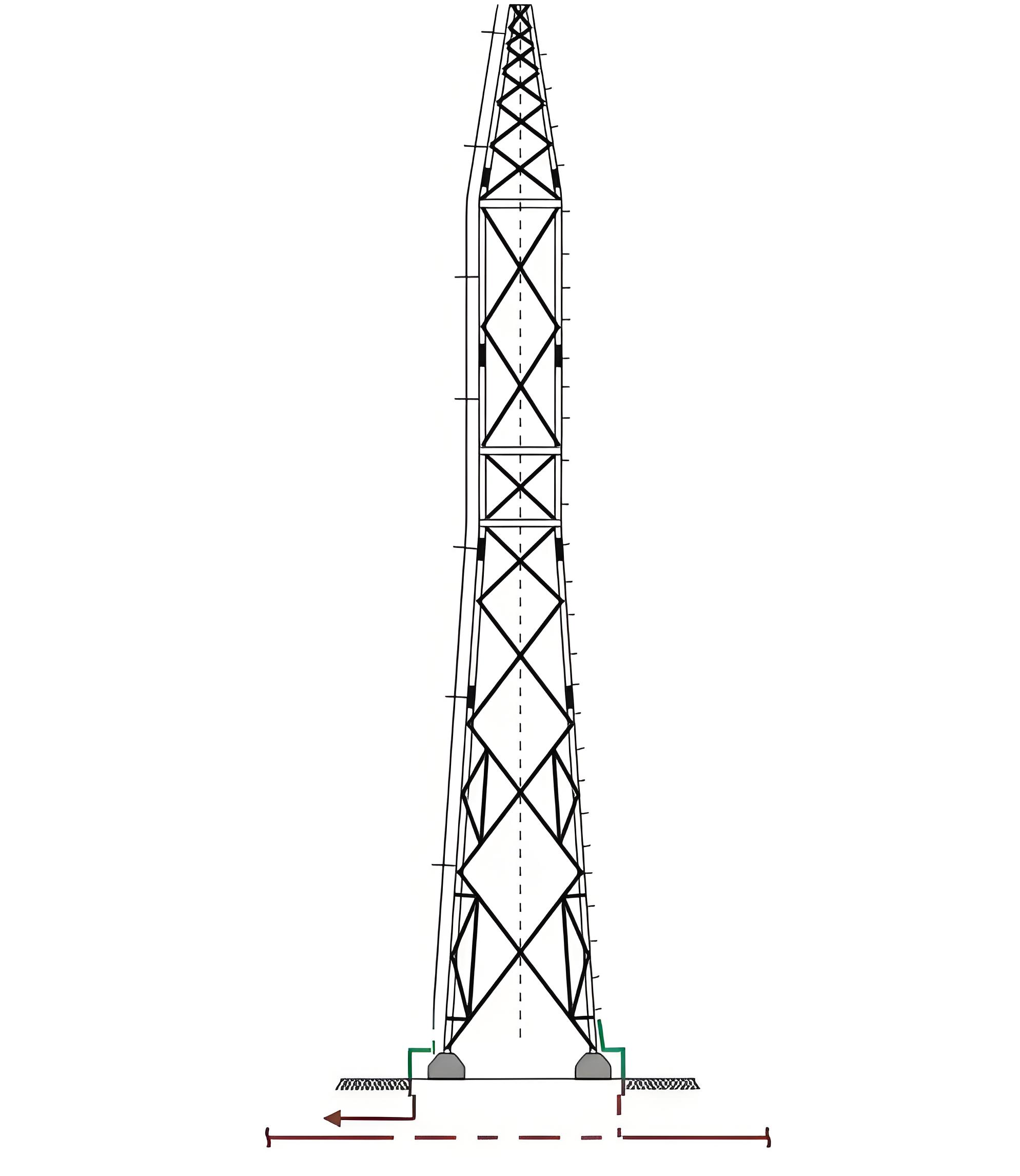
The shield wire comes down along the a leg of gantry structure. The shield wire which comes down along the a leg of gantry structure is referred as down comer. The downcomer is clamped with the leg members of the structure at every 2 meters intervals. This downcomer is connected with a earthing lead coming directly from a pipe earth electrode. Diagonally opposite leg of the same structure should directly be connected to the main earthing grid via riser.
Earthing of Bus Post Insulator
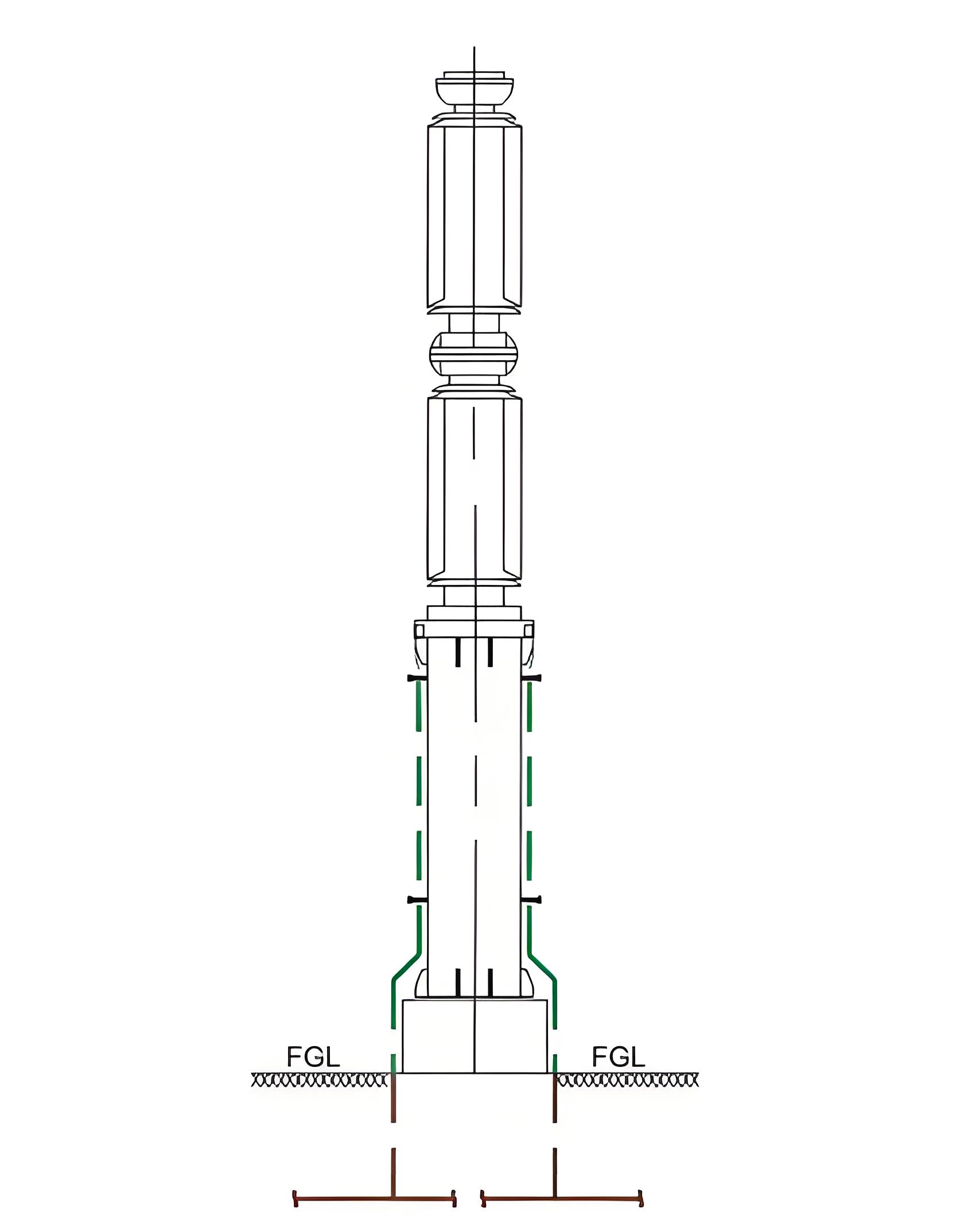
Each bus post insulator or BPI is connected to the main earthing grid via two risers. A 50 mm × 10 mm ms flat comes down along the BPI support structure from each of the two earthing points of BPI metallic base. These ms flats from base of the BPI are connected to the risers come from x and y conductor of main earthing grid.
Earthing of Current Transformer
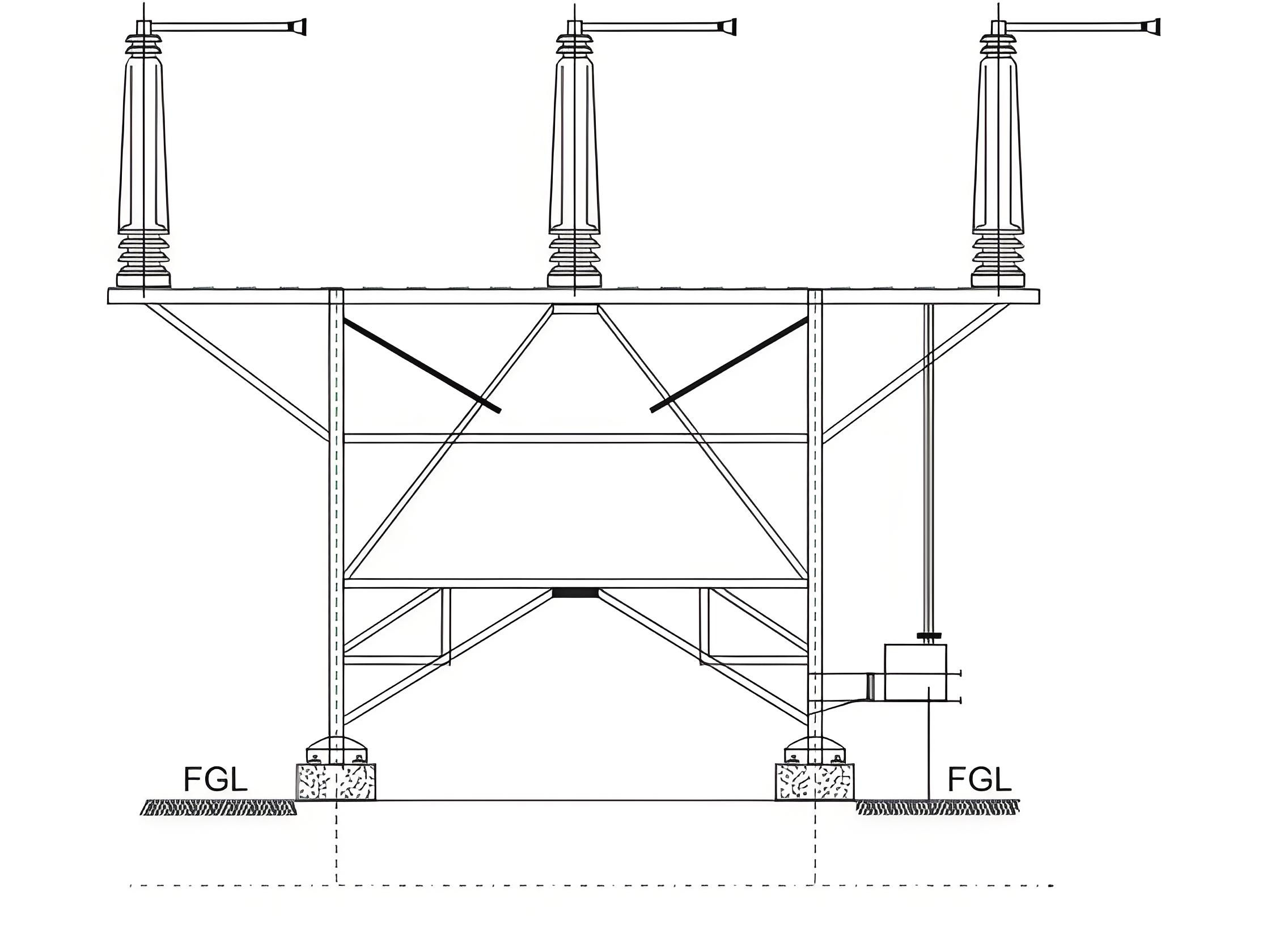
One 50 mm × 10 mm ms flat comes down along the a leg of current transformer support structure from metallic base of the CT. This is connected to the main earthing grid via riser. Diagonally opposite vertical leg members of the structure is connected to the main earthing grid via another riser. If first riser comes from x conductor of the ground grid then second riser must come from the rod conductor of y direction.
The CT junction box should also be connected to the main earthing grid from two points by means of 50 mm × 10 mm ms flats.
Earthing of Circuit Breaker
Supporting structure of each pole of a circuit breaker along with the metallic base of the poles are connected to the main earthing grid via two risers one preferably from x and other from y direction. The structure of the poles are connected together with 50 mm × 8 mm ms flat. The mechanism box of each pole is also connected to the main earthing grid via 50 mm × 10 mm ms flat.
Earthing of Isolator
The base of each pole of the isolator should be connected together with the help of one 50 mm × 10 mm ms flat. This ms flat will be connected to the main earthing grid via two risers one preferably from x and other from y direction earth mat conductors. The mechanism box of the isolator should be connected to the auxiliary earth mat and the auxiliary earth mat then connected to the main earthing grid to two different points on the main earthing grid.

Earthing of Lightning Arrestors
The base of the lightning arrestors must be connected to the main earthing grid via one riser and structure of the lightning arrestors must be connected to the main earthing grid via another riser. One extra earthing connection is provided in lightning arrestors which connects a treated earth pit via surge counter of the arrestors. This earth pit may be with test link.
Earthing of Capacitive Voltage Transformer
The base of the CVT or capacitive voltage transformer is connected to the main earthing grid via a riser. The special earthing point on the base of the CVT is connected to the pipe earth electrode with 50 mm × 8 mm ms flat. The bottom portion of the support structure is also connected to the main earthing grid via riser. Two opposite earthing points of the CVT junction box should also be connected to the main earthing grid.
Earthing of Cable Sealing System
The supporting structure of a cable sealing system should be connected to the main earthing grid via two risers. The earthing strip of size 50 mm × 10 mm ms flat must come down from the top of the supporting structure.
Earthing of Bay Marshalling Kiosk
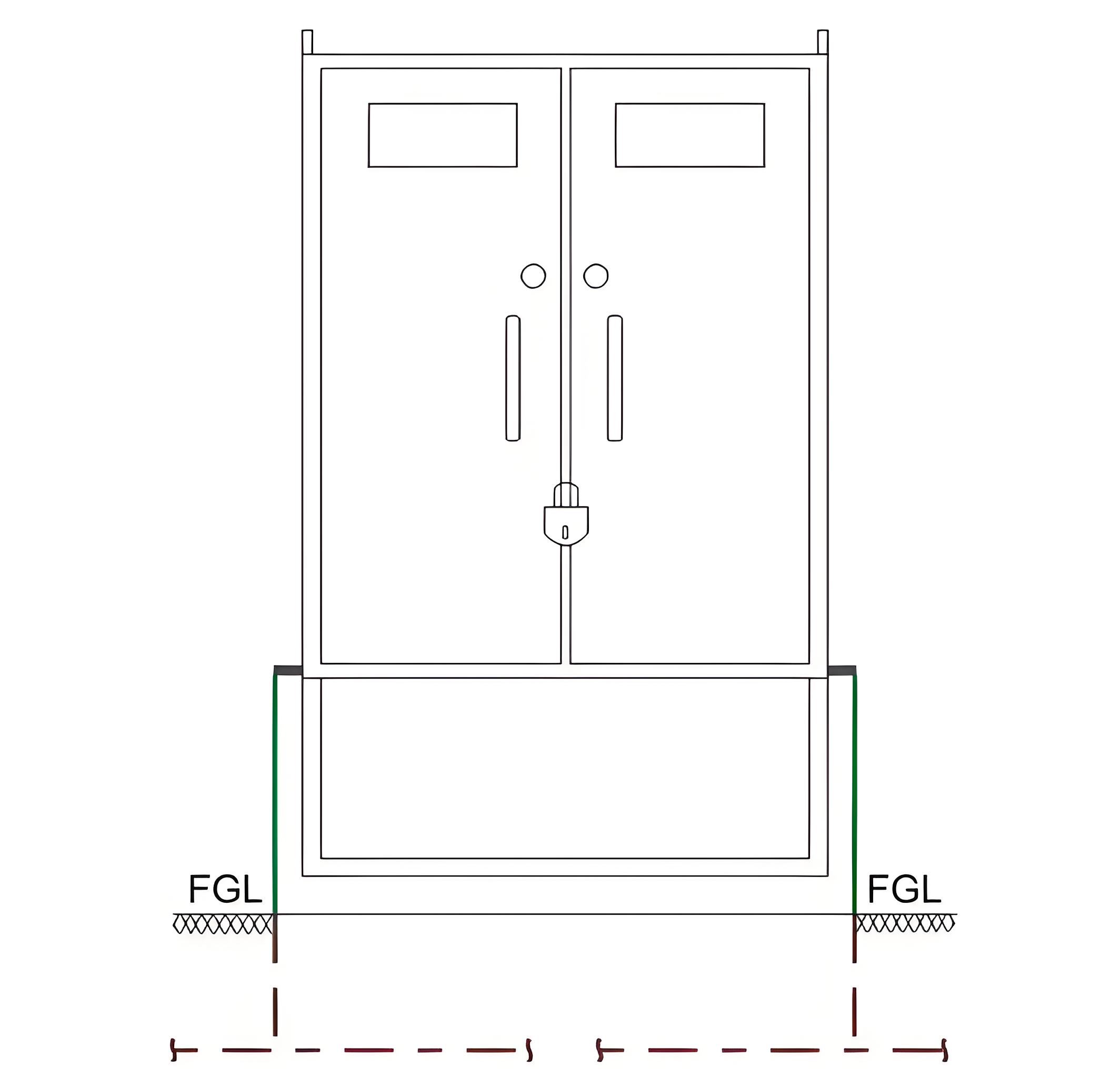
There are two protected leads provided on two opposite sides of the bay marshalling kiosk. These two points must be connected to the main earthing grid via two risers. These links are provided on the lower portion of the marshalling kiosk or box.
Earthing of Earthing Transformer
The base of the earthing transformer must be connected to the main earthing grid via two risers. The neutral point of the earthing transformer must be connected to the pipe earth electrode with a test link. The neutral to ground connection should go through a neutral current transformer for earth fault protection purpose.
The Electricity Encyclopedia is dedicated to accelerating the dissemination and application of electricity knowledge and adding impetus to the development and innovation of the electricity industry.
