What is Capacitive Voltage Transformer?
What is Capacitive Voltage Transformer?
Definition: A capacitive voltage transformer (CVT), also known as a capacitive potential transformer, steps down high - voltage input signals to provide low - voltage signals that can be easily measured by measuring instruments.
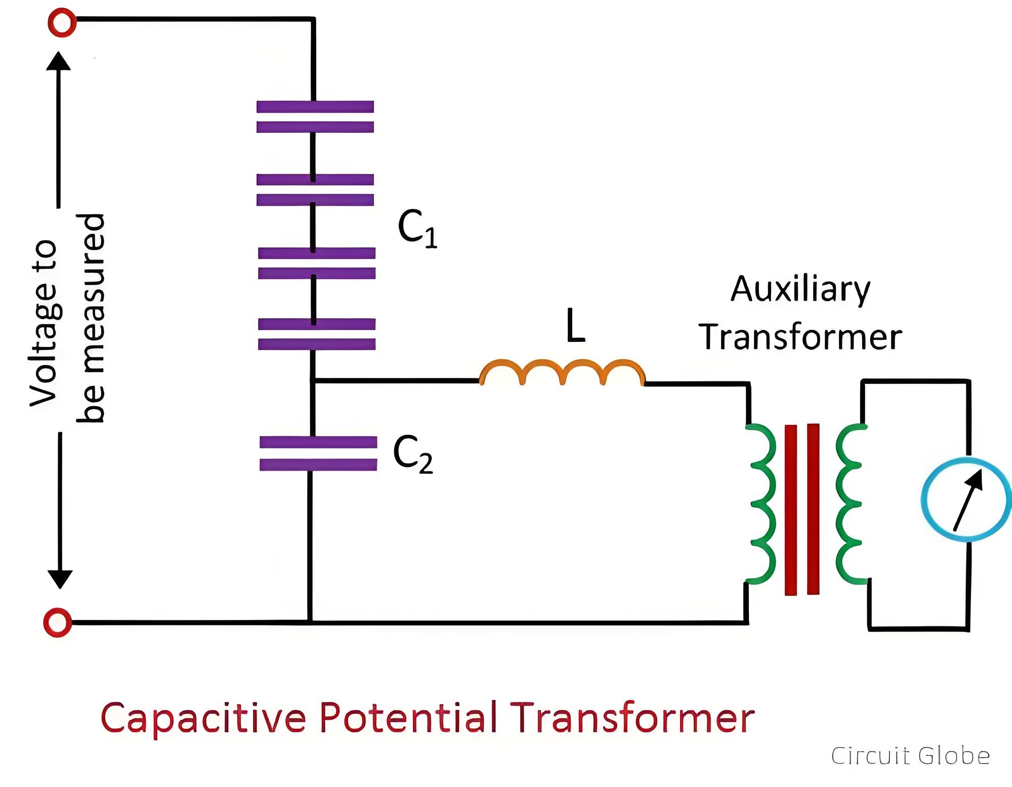
The capacitive potential divider, inductive element, and auxiliary transformer are the three main components of a capacitive potential transformer.
Why is a Capacitive Voltage Transformer (CVT) Needed?
When measuring high voltages above 100 kV, a highly - insulated transformer is required. Compared with ordinary transformers, highly - insulated transformers are quite costly. To cut costs, capacitive voltage transformers are employed in the system. CVTs are inexpensive, and their performance is not significantly inferior to that of highly - insulated transformers.
Working Principle of Capacitive Voltage Transformer
The capacitive potential divider is used in conjunction with the auxiliary transformer and the inductive element. The capacitive potential divider steps down extra - high - voltage signals to low - voltage signals. The output voltage of the capacitive voltage transformer is further stepped down with the aid of the auxiliary transformer.
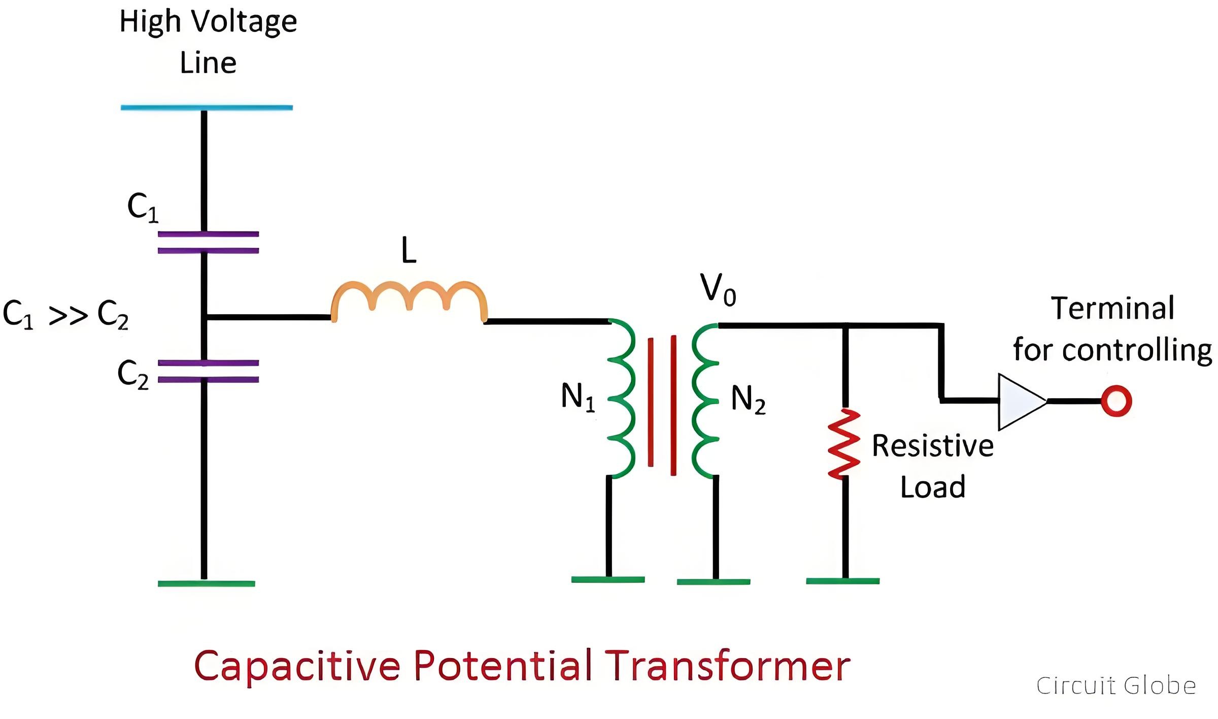
Refer to the circuit diagram of the capacitive voltage transformer.
Arrangement of Capacitor or Potential Divider
The capacitor or potential divider is connected across the line whose voltage is to be measured or controlled. Suppose C1 and C2 are the capacitors connected across the transmission line. The output of the potential divider serves as the input to the auxiliary transformer.
Compared with the capacitor placed near the transmission line, the capacitor placed near the ground has a higher capacitance value. A high capacitance value means that the impedance of that part of the potential divider becomes low. As a result, low voltages are transmitted to the auxiliary transformer. The auxiliary transformer further steps down the voltages.
N1 and N2 are the number of turns in the primary and secondary windings of the transformer respectively. The meter used to measure the low - voltage value is resistive, while the potential divider is capacitive. Therefore, a phase shift occurs, which affects the output. To solve this problem, an inductor is connected in series with the auxiliary transformer.This inductor L contains the leakage flux of the auxiliary winding of the auxiliary transformer. The value of the inductance is given by

The value of the inductance is adjustable. The inductance is utilized to compensate for the voltage drops that occur in the transformer due to the decrease in current from the potential divider. However, in practical operation, due to inductance losses, complete compensation cannot be achieved.The voltage transformation ratio of the transformer is expressed as

Since the value of C1 is larger than that of C2, the value of C1/(C1 + C2) is small, enabling the acquisition of a low voltage.The voltage transformation ratio of the capacitive potential transformer is independent of the burden. Here, the burden refers to the load carried by the secondary winding of the transformer

