Wien’s Bridge
Wien's Bridge: Applications and Challenges
Wien's bridge is a crucial component in AC circuits, primarily utilized for determining the value of unknown frequencies. It is capable of measuring frequencies within the range of 100 Hz to 100 kHz, with an accuracy level typically ranging from 0.1% to 0.5%. Beyond its frequency - measuring function, this bridge finds diverse applications. It is employed in capacitance measurement, serves as a key element in harmonic distortion analyzers, and is integral to high - frequency (HF) oscillators.
One of the defining characteristics of Wien's bridge is its sensitivity to frequency. This frequency - sensitivity, while useful for its intended measurement purposes, also presents a significant challenge. Achieving the balance point of the bridge can be a complex task. A major contributing factor to this difficulty is the nature of the input supply voltage. In practical scenarios, the input supply voltage is rarely a pure sinusoidal waveform; instead, it often contains harmonics. These harmonics can disrupt the balance condition of the Wien's bridge, leading to inaccurate measurements or preventing the bridge from reaching equilibrium altogether.
To address this issue, a filter is incorporated into the bridge circuit. This filter is connected in series with the null detector. By filtering out unwanted harmonics from the input signal, the filter helps to ensure that the voltage reaching the bridge more closely approximates a pure sinusoidal waveform. This, in turn, facilitates the attainment of a stable balance point and improves the overall accuracy and reliability of the measurements performed using Wien's bridge.
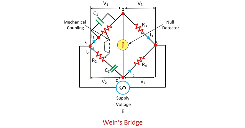
Analysis of the Balanced Condition of the Bridge
When the bridge reaches a balanced state, the electrical potential at nodes B and C becomes equal, that is, V1 = V2 and V3 = V4. The voltage V3, which is expressed as V3 = I1 R3, and V4 (where V4 = I2 R4) not only have the same magnitude but also the same phase, resulting in their waveforms overlapping perfectly. Moreover, the current I1 flowing through the arm BD, the current I2 passing through R4, as well as the voltage - current relationships I1 R3 and I2 R4, all exhibit in - phase characteristics.
The total voltage drop across the arm AC is the aggregate of two components: the voltage drop I2 R2 across the resistance R2 and the capacitive voltage drop I2/ ωC2 across the capacitance C2. In the balanced condition of the bridge, the voltages V1 and V2 match precisely in both magnitude and phase.
The phase of voltage V1 aligns with the voltage drop IR R1 across the arm R1, indicating that the resistance R1 is in the same phase as V1. The phasor addition of either V1 and V3 or V2and V4 yields the resultant supply voltage, reflecting the electrical equilibrium within the bridge circuit.
At the balance condition,

On equating the real part,

On comparing the imaginary part,

By substituting the value of ω = 2πf,

The slider of the resistance R1 and R2 mechanically connect to each other. So that, the R1 = R2 obtains.
The Electricity Encyclopedia is dedicated to accelerating the dissemination and application of electricity knowledge and adding impetus to the development and innovation of the electricity industry.
