Campbell’s Bridge

Edwiin
05/04/2025

Campbell Bridge: Definition and Function
Definition
The Campbell bridge is a specialized electrical bridge designed to measure unknown mutual inductance. Mutual inductance refers to the physical phenomenon where a change in the current flowing through one coil induces an electromotive force (emf) and, consequently, a current in a neighboring coil. This bridge is not only useful for determining mutual inductance values but can also be employed to measure frequency. It does so by adjusting the mutual inductance until a null point is achieved in the bridge circuit.
In electrical engineering, accurately measuring mutual inductance is crucial for understanding the interaction between different coils in circuits, such as in transformers, inductive coupling systems, and various electrical machinery. The Campbell bridge provides a precise and reliable method for these measurements. When used for frequency measurement, the null - point detection principle allows engineers to establish a relationship between the mutual inductance setting and the frequency of the electrical signal under test.
The following figure illustrates the concept of mutual inductance, which forms the foundation for the operation of the Campbell bridge.

Let:
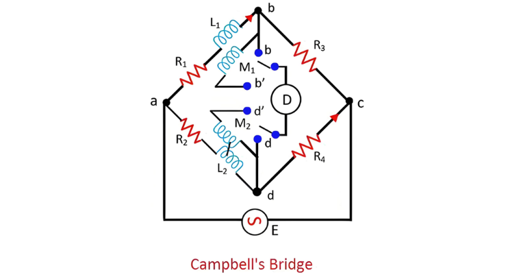
  • M1 represent the unknown mutual inductance
  • L1denote the self - inductance of the secondary of mutual inductance M1
  • M2signify the variable standard mutual inductance
  • L2 be the self - inductance of the secondary of mutual inductance M2
  • R1, R2, R3, R4 stand for non - inductive resistances
Achieving the balanced position of the Campbell bridge necessitates a two - step procedure:

Step 1: Initial Setup and First Balance Condition

The detector is initially connected between points ‘b’ and ‘d’. In this configuration, the circuit functions analogously to a simple self - inductance comme
  • First Balancing Step To bring the bridge to a balanced condition in the first stage, resistors R3 or R4, along with R1 and R2, are adjusted. This adjustment process fine - tunes the electrical parameters of the circuit, ensuring that the electrical potential differences across the relevant parts of the bridge are equalized, much like adjusting the weights on a balance scale to achieve equilibrium.
  • Second Balancing Step In the next phase, the detector is reconnected between points b' and d'. Building on the adjustments made in the first step, the variable standard mutual inductance M2 is then systematically varied. Through this process of varying M2 while maintaining the previously set resistor adjustments, the overall electrical configuration of the bridge is further optimized. Eventually, a balance point is reached, indicating that the bridge has achieved a state of equilibrium where the electrical signals in the circuit are in harmony, and accurate measurements of the unknown mutual inductance M1 can be made.


Edwiin

Classification of Electric Power Distribution Network Systems
The typical electric power system network is categorized into three main components: generation, transmission, and distribution. Electric power is produced in power plants, which are often located far from load centers. As a result, transmission lines are employed to deliver power over long distances.To minimize transmission losses, high-voltage power is used in transmission lines, and the voltage is reduced at the load center. The distribution system then delivers this power to end-users.Types
Edwiin
06/05/2025
Why is the Ground Wire Always Positioned Above the Overhead Power Lines?
Ground Wire in Overhead Transmission LinesThe ground wire (also called earth wire or OPGW) installed above phase lines in overhead transmission lines acts as a key protective and safety component. It provides lightning protection, ground fault defense, and helps prevent electrical system disruptions.In overhead transmission lines, positioning the ground wire above phase lines serves specific safety and performance purposes. Referred to as a "shield wire" or "static wire," this configuration has
Edwiin
06/04/2025
What is the Power Angle in a Power Transmission Line?
The power angle, denoted by δ, is the phase angle difference between two voltage levels in a power transmission line. Specifically, it represents the angular discrepancy between the sending-end voltage phasor and the receiving-end voltage (or between voltages at two bus points). In simpler terms, it quantifies the phase shift between voltage and current waveforms in the transmission line.Also referred to as the torque angle or load angle, this parameter is critical for two key reasons: it
Edwiin
06/04/2025
Permanent Magnet Moving Coil or PMMC Instrument
DefinitionInstruments that utilize a permanent magnet to generate a stationary magnetic field within which a coil moves are known as Permanent Magnet Moving Coil (PMMC) instruments. They operate on the principle that torque is exerted on a moving coil situated in the magnetic field of a permanent magnet. PMMC instruments provide accurate results for direct current (DC) measurements.Construction of PMMC InstrumentThe moving coil and the permanent magnet are the key components of a PMMC instrument
Edwiin
05/30/2025
Inquiry
Download
Experts Electrical is dedicated to serving the personnel in the global power industry.
Join Experts Electrical, not only can you discover power equipment and power knowledge, but also canhnd like - minded friends!