What is Earth Tester?
Definition:An earth tester is an instrument designed for measuring the resistance of the earth. In a power system, all equipment is connected to the earth via an earth electrode. The earth plays a vital role in safeguarding both the equipment and personnel from fault currents. The resistance of the earth is extremely low, allowing the fault current passing through the earth electrode to be safely dissipated into the ground, thus protecting the power system from damage.
Earth electrodes are also crucial for controlling the high potential that can occur in equipment due to powerful lightning surges and voltage spikes. Additionally, the neutral of a three - phase circuit is connected to the earth electrodes for added protection.
Before earthing equipment, it is essential to ascertain the resistance of the specific area where the earthen pit will be dug. The earth should have low resistance to enable the seamless passage of fault currents into the ground. An earth tester is used to determine this earth resistance.
Construction of Earth Tester
The earth tester is equipped with a hand - driven generator. Its two main components are the rotational current reverser and the rectifier, both of which are mounted on the shaft of the DC generator. Due to the presence of the rectifier, the earth tester operates solely on DC power.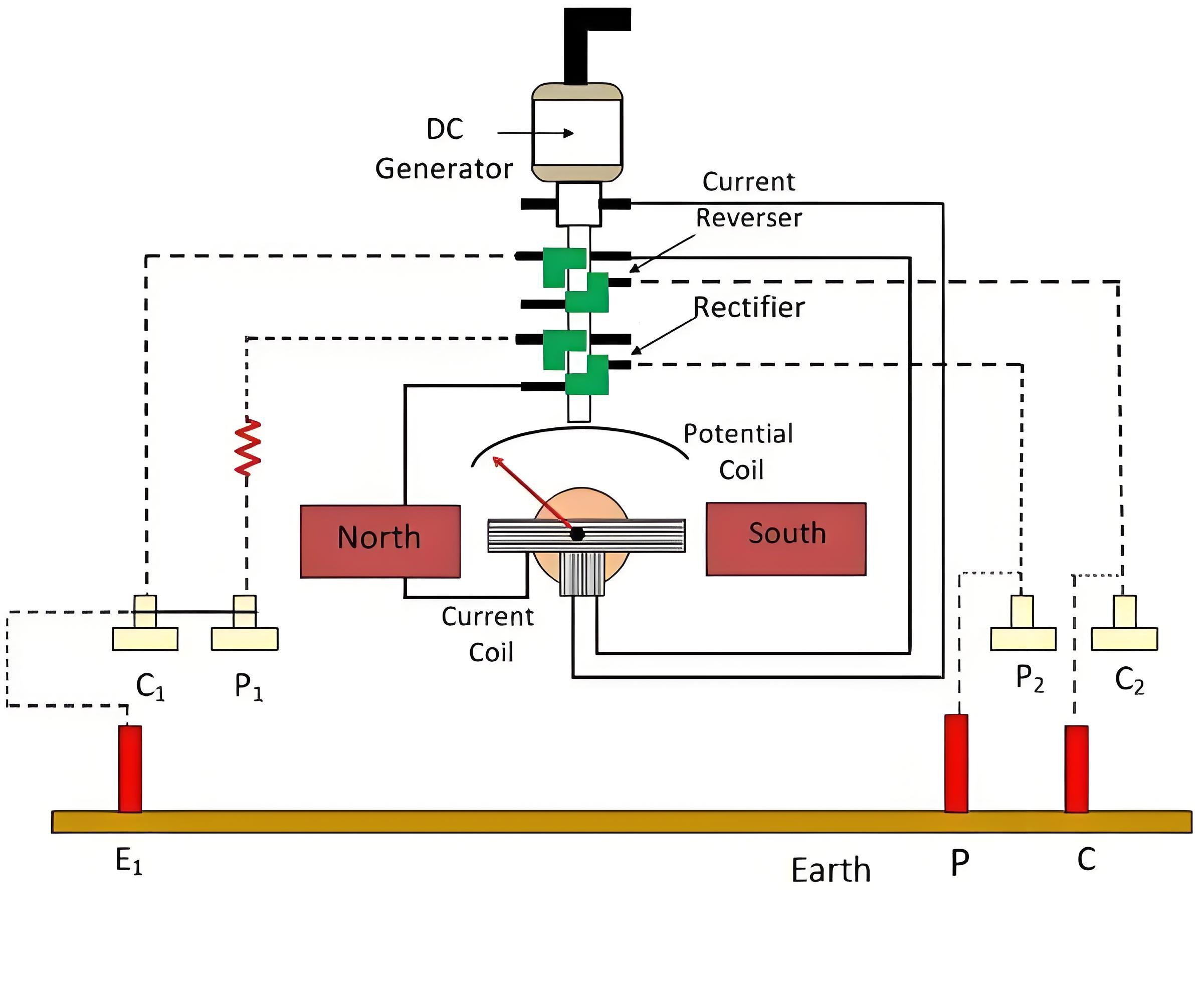
The earth tester is equipped with two commutators, which are installed alongside the current reverser and rectifier. Each commutator is composed of four fixed brushes. A commutator is a device employed to change the direction of current flow. It is connected in series with the armature of the generator. The brushes serve to transfer power from the stationary components to the moving parts of the device.
The brushes are arranged in such a manner that, even after the commutator rotates, they are alternately connected to one of the segments. The brushes and commutators are always in a connected state with each other.
The earth tester incorporates two pressure coils and two current coils. Each coil has two terminals. A pair consisting of a pressure coil and a current coil is positioned across a permanent magnet. One pair of the current and pressure coils is short - circuited and connected to the auxiliary electrodes.
One end terminal of the pressure coil is linked to the rectifier, and its other end is connected to the earth electrode. Similarly, the current coil is connected to both the rectifier and the earth electrode.
The earth tester also has a potential coil that is directly connected to the DC generator. The potential coil is placed between the permanent magnet. This coil is connected to a pointer, and the pointer is mounted on a calibrated scale. The pointer indicates the magnitude of the earth resistance. The deflection of the pointer is determined by the ratio of the voltage across the pressure coil to the current in the current coil.
The short - circuit current that passes through the equipment and into the earth is of an alternating nature. Therefore, it can be stated that alternating current flows in the soil. This alternating current mitigates the undesirable effects in the soil, which may be caused by chemical reactions or the generation of back electromotive force (emf).
The Electricity Encyclopedia is dedicated to accelerating the dissemination and application of electricity knowledge and adding impetus to the development and innovation of the electricity industry.

