Steam Calculator: How To Calculate Steam Consumption

What is Steam Consumption in a Pipe?
Steam consumed and steam utilized at the point of application are not equal. Normally steam consumed or generated in a steam boiler is more than what is required for use at the point of application.
The difference in steam consumption and steam utilization is due to:
Steam condensation when it travels on its way to point of use mainly due to exposed surfaces.
Leakages (if any)
When steam condenses on the wall of an exposed/uninsulated steam pipe, it gives up its enthalpy of evaporation.
Proper utilization of steam helps in saving in the input cost of water and coal. Saving of each kg of steam is directly proportional to the saving of some percentage of water, coal and electricity.
Calculation of steam consumption in a pipe during the start-up operation and normal continuous operation is possible, and will be discussed in detail below.
Steam Consumption in Steam Mains
Steam consumption within the pipe system needs to be judiciously monitored and controlled. The rate of condensation of the steam in the steam piping network depends upon the type of load (i.e. warm-up load or running load).
The rate of condensation of steam needs to be taken into account for sizing the steam traps, and also in finalizing the boiler output.
What is Warm-Up Load ?
During the plant start-up after a long time or from cold, then the steam is required to heat the system uniformly to bring the system close to the normal working temperature of the system.
The ‘warm-up load’ is the steam load which is associated with the steam consumption during the start-up of the plant. This can be either from the cold shut down, or from start-up after a very long time.
The rate of condensation of steam during the warm-up period is maximum. The design of steam trap shall be based on this load.
A good practice is to warm-up the system very slowly for safety-reasons, pipes have the benefit of reduced thermal and mechanical stress. Thus results in the following benefits:
Eliminations of leaks
Lower-maintenance-costs
Longer life for the pipes
No water hammer.
What is Process Plant Running Load?
Process plant running load is the steam load which is related to the normal (full load) continuous load of the plant. The rate of condensation of steam during the full load running a load of the plant is minimum.

How to Warm-Up a System?
Uniform and slow system warm-up can be achieved by a small by-pass valve in parallel to the main line isolation valve.
The time required to warm up the pipe network decides the warm-up (bypass) valve size. This valve can be a manual or automatic type depending on the user/client.
It is always better to discourage the practice of using the main valve for warm-up instead of the bypass valve. Since the main valve is far bigger in size (designed for full flow requirement) and not appropriate to use for small flow during the warm-up period.
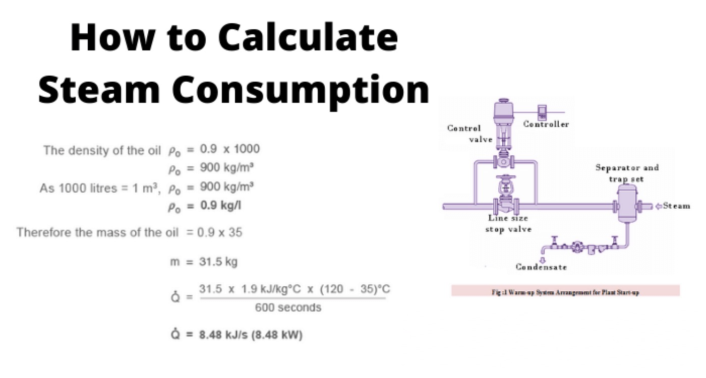
As shown in figure1 above, before the main valve/bypass valve separator is installed to ensure that steam passing through the valve should be dry to protect the valve wear and tear.
If we provide sufficient time for the warming-up, then it is possible to get the following benefits:
For minimizing the pipe stress
For operational safety
Reduce start-up loads on boiler
The steam flowrate required to bring a pipework system up to operating temperature is a function of:
Mass
Specific heat of the material
Temperature increase
Enthalpy of evaporation of steam or Enthalpy of saturated steam
Allowable time

Where:
ms: Mean rate of condensation of steam in kg/hr
W: Total weight of pipe plus flanges and fittings in kg
Ts: Steam temperature oC
Tamb: Ambient temperature
Cp: Specific heat of pipe material in kj/kgoC
hfg: Enthalpy of evaporation or saturated enthalpy at operating pressure in kj/kg
t: Time of warming-up in minutes
Note: Suppose if the warm-up/heating time of the system is increased to 12 minutes from 6 minutes, then the initial flow rate of the steam can easily be reduced to half. If the warm-up/heating time of the system is increased to say 24 minutes, then the initial steam flow rate for heating can be reduced further.
Method to calculate the warm-up condensing load for a period of 30 minutes in a steam system
Let:
The system consists of carbon steel pipe of size — 150 mm
Steam Pressure — 16 bar(g)
Steam temperature (Ts) — 201oC
Enthalpy of evaporation corresponding to above parameters hfg — 1933
Ambient air temperature (Tamb) — 20oC
Length of the pipe shall be — 120 m
Cp of steel is —- 0.49 kj/kgo C
Warming-up time in minutes (t) — 30
Total weight of pipe plus flanges and fittings in kg (W)
Pipe network consists of 10 pairs of PN-40 flanged joints and two isolation valves
Table 1: Typical weights of steel pipe, flanges and bolts, and isolating valves in kg.
Pipe size(mm) |
Sch.40 pipe kg/m |
Flange weight per pair |
Isolating valve flanged PN40 |
||
PN40 |
ANSI150 |
ANSI300 |
|||
150 |
28.2 |
28.0 |
26.0 |
32 |
88 |
To find W, find the mass of the various steam main items from Table 1
150 mm steel main = 28.2 kg/m
150 mm flanges to PN-40 = 28 kg per pair
150 mm stop valve = 88 kg each

Rate of condensation generated during warm-up time is given by:

Statement: Respect the original, good articles worth sharing, if there is infringement please contact delete.
Electrical4U is dedicated to the teaching and sharing of all things related to electrical and electronics engineering.


