Stirling Boiler

Electrical4u
03/20/2024

WechatIMG1834.jpeg

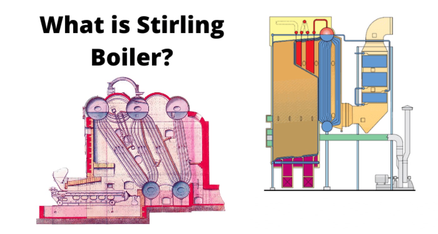
Stirling Boiler is one of the most basic variety of bent tube boiler. In most of the modern thermal power generating plants we use bent tube boiler. Stirling Boiler is one of the largest capacity boiler. A Stirling Boiler can generate as high as 50,000 kg steam per hour and can produce pressure as high as 60 kgf per cm2. This boiler was first designed in the year of 1888 by Alan Stirling so we refer the boiler as Stirling Boiler. Because of the huge capacity we can use this boiler in central power stations.

In Stirling Boiler there are three steam drums and two mud drums. Three steam drums are placed on the top portion of the boiler system structure and two mud drums are placed on bottom of the structure. The top steam drums are connected to the bottom mud drums with banks of bent tubes. Since the tubes are bent, the mechanical stresses due to expansion of the pipes during heating can not effect the system much. The steam drums, mud drums and bent tubes are made of steel. Also still structure is used to support the entire system.

The entire system is enclosed by a brickwork. Here the brick enclosure is used to prevent the heat dissipation to the surroundings. The fire door is constructed at the bottom side of the brick enclosure wall. The damper is provided on the other side of the brick enclosure wall to take out the combustion gas as when required.

The fire brick arch is provided above the furnace. Three baffles are provided in the boiler system to allow the combustion gas to flow in zigzag way. There is one water circulating tubes connecting the mud drums. Also there are steam circulating tubes connecting middle steam drums to outer steam drums. There is also a group of hot water circulating tube from front steam drum to middle steam drum.

A safety value is provided on the back steam drum. Finally the steam is collected from middle steam drum. The steam compartment is constructed inside the middle steam drum. The super heater is connected to steam compartment through a steel pipe.
stirling boiler

Statement: Respect the original, good articles worth sharing, if there is infringement please contact delete.

Electrical4u

Electrical4U is dedicated to the teaching and sharing of all things related to electrical and electronics engineering.

Classification of Electric Power Distribution Network Systems
The typical electric power system network is categorized into three main components: generation, transmission, and distribution. Electric power is produced in power plants, which are often located far from load centers. As a result, transmission lines are employed to deliver power over long distances.To minimize transmission losses, high-voltage power is used in transmission lines, and the voltage is reduced at the load center. The distribution system then delivers this power to end-users.Types
Edwiin
06/05/2025
Why is the Ground Wire Always Positioned Above the Overhead Power Lines?
Ground Wire in Overhead Transmission LinesThe ground wire (also called earth wire or OPGW) installed above phase lines in overhead transmission lines acts as a key protective and safety component. It provides lightning protection, ground fault defense, and helps prevent electrical system disruptions.In overhead transmission lines, positioning the ground wire above phase lines serves specific safety and performance purposes. Referred to as a "shield wire" or "static wire," this configuration has
Edwiin
06/04/2025
What is the Power Angle in a Power Transmission Line?
The power angle, denoted by δ, is the phase angle difference between two voltage levels in a power transmission line. Specifically, it represents the angular discrepancy between the sending-end voltage phasor and the receiving-end voltage (or between voltages at two bus points). In simpler terms, it quantifies the phase shift between voltage and current waveforms in the transmission line.Also referred to as the torque angle or load angle, this parameter is critical for two key reasons: it
Edwiin
06/04/2025
Permanent Magnet Moving Coil or PMMC Instrument
DefinitionInstruments that utilize a permanent magnet to generate a stationary magnetic field within which a coil moves are known as Permanent Magnet Moving Coil (PMMC) instruments. They operate on the principle that torque is exerted on a moving coil situated in the magnetic field of a permanent magnet. PMMC instruments provide accurate results for direct current (DC) measurements.Construction of PMMC InstrumentThe moving coil and the permanent magnet are the key components of a PMMC instrument
Edwiin
05/30/2025
Inquiry
Download
Experts Electrical is dedicated to serving the personnel in the global power industry.
Join Experts Electrical, not only can you discover power equipment and power knowledge, but also canhnd like - minded friends!