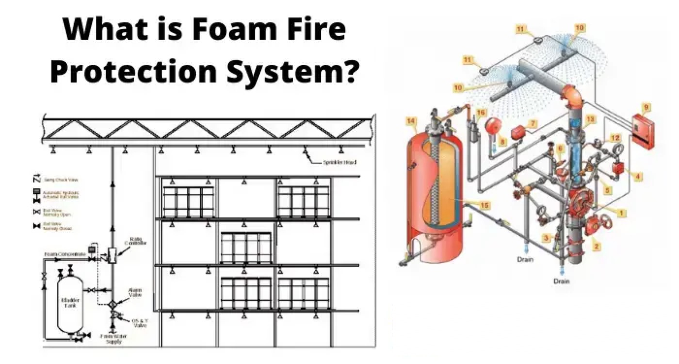
Foam Fire Protection System

Foam Fire Protection System is fire suppression system. Its success is mainly depends on proper mixing of foam concentrate along with air and water, to form a uniform foam blanket to extinguish flame.
Back Ground of Foam Fire Protection System
Water is known for suppressing fires, but unfortunately not best in all the cases. Water is not effective on an oil fire, and can be of no use during emergency. To suppress oil fire foam is reliable to use, since it prevent the direct contact of fire with oxygen, resulting in suppression of the combustion.
Application of Foam Fire Protection System
Foam Fire Protection System is designed for countering the oil (light diesel oil/Heavy furnace oil) fuel fires. Often foam protection is used for protecting oil tank and extinguishing fire in oil tanks.
Foam system serves two purposes, first to extinguish fire in oil tank and the second function is to cool the tank from outside by installing close circular pipelines around the tank and maintaining the temperature under control in case of neighboring tank fire. This is very helpful in preventing the fire spread from one tank to another.
Foam Fire Protection System Comprises of
The concentration of the foam is an important factor in this system. It comprises of foam concentration tank, proportioning device, automatic controlling valves, controlling panel, foam producer, discharge outlet etc.
System Tank – for storing the foam, tank can be of cylindrical vertical or horizontal type stainless steel.
Proportioning Devices – for discharging the sufficient amount of foam- concentrate into the spray-water based on specific requirement. These devices are sized and designed keeping in mind the minimum loss of pressure.
Foam-chambers.
Automatic Foam Protection system mainly includes all areas where fuel oil storage tanks are built.
Apart from this, it covers all the sensitive areas of the power plant where hydrant system and spray system do not perform fairly.

Foam Fire Protection System Design Principles
Given below are the design basics which need to be given due importance before installing Foam system:
The fixed foam system operates automatically with the assistance provided by a fire detection system around the tank. The Automatic Foam system forms a network pipe near all the fuel oil storage tanks.
The complete system should be designed as per NFPA-11 regulations.
Concentration of foam is a very important factor and it should be 100 % AFFF type, and stored in a tank of double of its capacity and it is discharged through a foam pump of capacity of 200 %.
The minimum effective capacity of each foam concentrate tank and foam pumps should be designed for the protection of one largest fuel oil tank at its design capacity for a minimum duration of 60 minutes.
Automatic foam protection system covers an area of oil storage tank and its surroundings. As fire detection system sense any smoke in the surroundings, automatic foam protection system starts working automatically.
Foam concentrate will be sucked by the 2 foam inductors of 100% capacity, one of motor driven and another of diesel engine driven pump.
Special attention shall be given for foam pumps material and the complete system should be designed as per the TAC norms.
The minimum effective capacity of foam concentrate tank should keep in consideration while designing and there should be an extra margin of 10 % over the calculated capacity.
The material used for making tanks shall be of carbon steel of Grade ‘B’ and there should be inner lining of 2 mm of FRP.
LDO tanks should be well equipped with foam proportioner.
Water required for foam system is supplied by hydrant system mains.
Supply line of oil tanks should be equipped with automatic solenoid at the upstream of foam proportioner.
In foam protection system, the network of pipelines has been done over the ground on RCC foundation.
Foam carrying pipelines should be of stainless steel.
For fixed roof type tanks, foam application rate should be 3% and foam solution shall be 6 lpm/sq.m.
Special components like non-return valves, strainers and isolation valves of pumps etc. should be used to avoid mixing of water with foam concentration.
Strainers should be used at the water inlet point so that raw impurities could be captured there and non-return valve in the pipelines avoids mixing of water with foam.
Statement: Respect the original, good articles worth sharing, if there is infringement please contact delete.
Electrical4U is dedicated to the teaching and sharing of all things related to electrical and electronics engineering.


