Hydrant System for Power Plant Fire Protection

Power Plant Fire Protection System (Part-II of III)
This section comprises of water based fire protection system called hydrant system in thermal power plants.
Flow Scheme for a Typical 660 MW Unit
Hydrant System
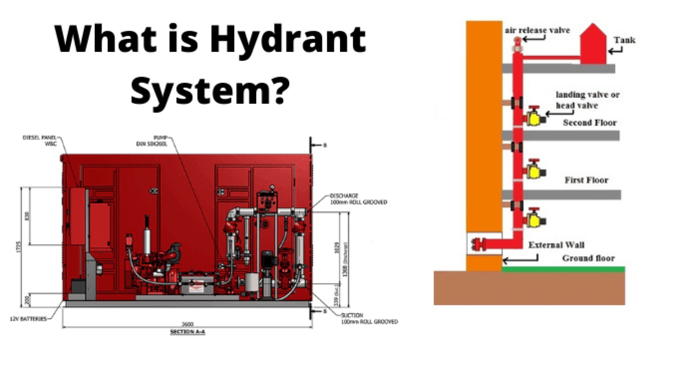
Hydrant system shall consist of a fire water ring main network of piping along with:
Isolation gate valves installed above ground on RCC pedestals around areas to be protected.
Hydrant valves (external/internal)
Hose cabinets
Couplings
Branch pipe
Nozzles and water monitors along with all accessories.
Other accessories like MS painted hose box shall be provided as per TAC.
External hydrants Hose houses or hose boxes shall be located all around the periphery of buildings and internal hydrants “hose box” shall be provided at each landing floor of staircases through above ground main.
Fixed Water Monitors (outdoor type) shall be provided for:
ESP areas,
Boiler house
Tall building
Coal stock pile area
Bunker building
Junction tower/transfer towers and
Other areas in the coal conveyor at locations where water can’t reach from hydrant system.
Hydrant System Requirements
Hydrant system requirements shall be designed keeping the following aspects of design in mind in line with the TAC requirements:
The hydrant network shall be sized to ensure that about 3.5 Kg/cm2 pressures are available at the hydraulically remotest point (as per TAC) in the system with the hydrant pump discharging the flow at rated pump capacity and head.
The velocity in the hydrant main shall not exceed 5.0 m/s.
At least two hydrants shall be provided with separate ring main for the main plants.
Spacing of each outdoor hydrant shall be provided 45 meters distance. The internal hydrant/landing valves shall be provided 45 meters distance in case of TG halls, Mill bay, Boiler and other area 30 Meters distance at each floor space.
Building shall be deemed to be protected by a hydrant if the hydrant is within 15 meters of the building.
Each of the landing valves and external hydrant valves associated with the main plant like transformer yard, TG building and Boiler area to be provided with a hose box.
Each ring mains to be terminated with an isolation valve and a blind flange at all the corners to enable future expansion/modification.
Fire water booster system pump head shall be designed for farthest top most point of the boiler and pressure will be tested at that elevation.
All the landings of boiler staircase, turbine buildings and other multi-storied structures, coal handling plant transfer points/junction towers, crusher house, bunker floors and other auxiliary buildings/non-plant buildings shall be provided with landing valves with hose box including the hose reels.
Spray System
The spray system works automatically. The deluge valves are operated and controlled by fire detection devices i.e. quartzite bulb detectors or by some other means of fire detection. The system could be pressurized till to the Deluge valves.
It covers all transformers located area, turbine and its auxiliaries, all oil storage tanks, cooling units and purifiers units. The equipment used in the whole system is spray pumps, the pressure controlling unit, variety of valves and strainers. There are two methods of spray system:
High Velocity Water spray system (HVWS system)
Medium Velocity Water spray system (MVWS system)
High Velocity Water Spray System (HVWS)
HVWS shall be designed as per TAC regulations. HVWS shall consists of above group piping, along with relevant fittings, deluge valves, isolation gate valves, spray nozzles, Quartzite bulb detector and pressure switches. HVWS system shall be equipped with the provision of automatically detect, control & extinguish any outburst of fire. The system shall allow hydraulically open the deluge valve thus allowing water to be sprayed on the equipment/area through projector nozzles in the form of a solid conical emulsifying spray.
Isolation gate valve and y-type strainer shall be provided on upstream and downstream side of the deluge valve. Fast acting butterfly valve shall be provided as a by-pass to deluge valve, so that this valve can be kept closed and can be operated manually in case of malfunction of deluge valve.

The pressure at the hydraulically most remote point in the network shall not be less than 3.5 bars for outdoor transformers as per TAC.
Placing of spray nozzles shall be such that their spray nozzles should cones overlap each other.
Areas covered under HVWS are:
All oil filled Generator transformers and its surrounding areas.
Unit auxiliary transformers.
Unit transformers.
Station auxiliary transformers.
Stand-by maintenance transformers.
Bus reactors.
CHP auxiliary transformers.
AHP auxiliary transformers.
Station transformer (transformer rating 10 MVA and above).
All type of oil storage tanks.
Oil coolers and purifiers unit.
Boiler’s burner and its surroundings.
Turbine Lube oil storage tanks and Turbine Oil purifier.
Clean and dirty lube oil tanks.
Boiler Feed Pumps lube oil tanks, coolers, consoles etc.
Turbine Oil canal pipelines in main plant.
Fuel Oil Pressurizing and Heating Units
Statement: Respect the original, good articles worth sharing, if there is infringement please contact delete.
Electrical4U is dedicated to the teaching and sharing of all things related to electrical and electronics engineering.


