Solar Cell: Working Principle & Construction (Diagrams Included)

What is a Solar Cell?
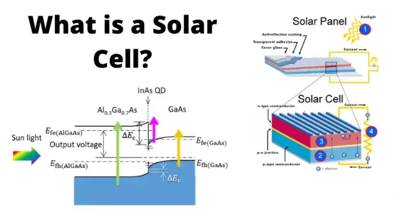
A solar cell (also known as a photovoltaic cell or PV cell) is defined as an electrical device that converts light energy into electrical energy through the photovoltaic effect. A solar cell is basically a p-n junction diode. Solar cells are a form of photoelectric cell, defined as a device whose electrical characteristics – such as current, voltage, or resistance – vary when exposed to light.
Individual solar cells can be combined to form modules commonly known as solar panels. The common single junction silicon solar cell can produce a maximum open-circuit voltage of approximately 0.5 to 0.6 volts. By itself this isn’t much – but remember these solar cells are tiny. When combined into a large solar panel, considerable amounts of renewable energy can be generated.
Construction of Solar Cell
A solar cell is basically a junction diode, although its construction it is little bit different from conventional p-n junction diodes. A very thin layer of p-type semiconductor is grown on a relatively thicker n-type semiconductor. We then apply a few finer electrodes on the top of the p-type semiconductor layer.
These electrodes do not obstruct light to reach the thin p-type layer. Just below the p-type layer there is a p-n junction. We also provide a current collecting electrode at the bottom of the n-type layer. We encapsulate the entire assembly by thin glass to protect the solar cell from any mechanical shock.
Working Principle of Solar Cell
When light reaches the p-n junction, the light photons can easily enter in the junction, through very thin p-type layer. The light energy, in the form of photons, supplies sufficient energy to the junction to create a number of electron-hole pairs. The incident light breaks the thermal equilibrium condition of the junction. The free electrons in the depletion region can quickly come to the n-type side of the junction.
Similarly, the holes in the depletion can quickly come to the p-type side of the junction. Once, the newly created free electrons come to the n-type side, cannot further cross the junction because of barrier potential of the junction.
Similarly, the newly created holes once come to the p-type side cannot further cross the junction became of same barrier potential of the junction. As the concentration of electrons becomes higher in one side, i.e. n-type side of the junction and concentration of holes becomes more in another side, i.e. the p-type side of the junction, the p-n junction will behave like a small battery cell. A voltage is set up which is known as photo voltage. If we connect a small load across the junction, there will be a tiny current flowing through it.
V-I Characteristics of a Photovoltaic Cell

Materials Used in Solar Cell
The materials which are used for this purpose must have band gap close to 1.5ev. Commonly used materials are-
Silicon.
GaAs.
CdTe.
CuInSe2
Criteria for Materials to be Used in Solar Cell
Must have band gap from 1ev to 1.8ev.
It must have high optical absorption.
It must have high electrical conductivity.
The raw material must be available in abundance and the cost of the material must be low.
Advantages of Solar Cell
No pollution associated with it.
It must last for a long time.
No maintenance cost.
Disadvantages of Solar Cell
It has high cost of installation.
It has low efficiency.
During cloudy day, the energy cannot be produced and also at night we will not get solar energy.
Uses of Solar Generation Systems
It may be used to charge batteries.
Used in light meters.
It is used to power calculators and wrist watches.
It can be used in spacecraft to provide electrical energy.
Conclusion: Though solar cell has some disadvantage associated it, but the disadvantages are expected to overcome as the technology advances, since the technology is advancing, the cost of solar plates, as well as the installation cost, will decrease down so that everybody can effort to install the system. Furthermore, the government is laying much emphasis on the solar energy so after some years we may expect that every household and also every electrical system is powered by solar or the renewable energy source.
Statement: Respect the original, good articles worth sharing, if there is infringement please contact delete.
Electrical4U is dedicated to the teaching and sharing of all things related to electrical and electronics engineering.


