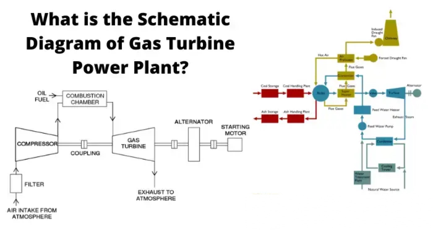
Schematic Diagram of Gas Turbine Power Plant

The main components of a gas turbine power plant are the
compressor,
regenerator,
combustion chamber,
gas turbine,
alternator, and
starting motor.
Compressor
Air compressor used in a gas turbine power plant is mainly of the rotary type. The air filter is attached at the inlet of the compressor where air gets filtered from dust. The rotary blades attached to the shaft push the air between stationary blocks, and consequently, the pressure of the air is increased. High pressure air is available at the outlet of the compressor.
Regenerator
There is always some heat presents in the exhaust gases in a gas turbine power plant. A portion of this heat is utilized in the regenerator. In regenerator, there is a net of fine tubes. The compressed air is passed through these fine tubes. The whole arrangement is enclosed in a vessel through which hot exhaust gases from turbine pass. During passing through the fine tubes, compressed air gets a portion of heat carried by exhaust gases. In this way, a significant portion of the heat of exhaust gases raises the temperature of the compressed air before it enters into the combustion chamber.
Combustion Chamber
After passing through the regenerator, the hot compressed air enters into the combustion chamber. In the combustion chamber, there are burners through which fuel oil is injected in the form of oil spray. Due to combustion of this hot oil spray inside the combustion chamber, the air attends a very high temperature. The temperature is about 3000oF. The compressed air mixed with combustion gases then cooled down to 1500oF to 1300oF before it is being delivered to the turbine for doing mechanical work there.

Alternator
The rotor of an alternator is attached to the same shaft of the turbine hence the alternator rotates along with the turbine and produces electrical energy.
Starting Motor
In gas turbine power plant the compressor, alternator, and turbine are attached to the same shaft. For starting the system, the compressor has to deliver pre-compressed air at starting. The shaft has to rotate to produce required compressed air for starting purpose. Hence, an alternative arrangement is required to run the compressor before the system is being started. This is done by a starting motor connected to the same shaft. A motor coupled with the main shaft supplies the required mechanical power for compressing air before starting.
Turbine
The compressed air mixed with combustion gases then enters in the turbine through nozzles. Here, the mixture of gases is suddenly expanded and it gains required kinetic energy to do mechanical work to rotate the turbine shaft (main shaft). In the turbine the temperature of the gases comes down to 900oF.
Statement: Respect the original, good articles worth sharing, if there is infringement please contact delete.
Electrical Operations provides detailed insights into safe and efficient electrical procedures, guiding practitioners through every step of handling electrical systems.


