Steam Turbine

The steam turbine is a favourite prime mover in a steam power generating plants. The steam turbine may be of capacity from 5 megawatts 2000 megawatt.
The advantages of a steam turbine over a diesel engine are as follows.
The size of a steam turbine is much smaller than that of an equivalent diesel engine. The size of a 30-megawatt steam turbine is same as a 5-megawatt diesel engine.
Construction wise the steam turbine is much simpler than a diesel engine. The rotor shaft, blades, steam control valve are the three essential components of a steam turbine.
A steam turbine suffers from less vibration than that of diesel engine if the rotating parts of the system correctly installed and aligned.
The speed of a steam turbine can be much higher than that of a diesel engine. The standard speed of a steam turbine used in an electrical generating station is 3600 RPM in USA and 3000 RPM in the UK whereas the highest standard speed of a diesel engine used for the same purpose is 200 RPM.
Control of steam turbine is much simpler than that of a diesel engine. A control valve is utilised for the purpose. The valve is fitted at the inlet line of the steam. This control valve governs the flow of steam to the turbine. There is one stop valve installed before the control valve. The function of stop valve is to block the entire flow of steam to the turbine in the event of any abnormality. The stop valve is an emergency valve.
The steam enters into the turbine at high pressure and temperature. After doing the desired work of rotating the rotor the steam exhausts at much lower pressure and temperature. The steam may enter in the turbine at a pressure and temperature of 1800 Pa, and 1000oF respectively and the pressure and temperature of the exhausting steam may be 1 Pa and 100oF respectively.
Working Principle of Steam Turbine
In a reciprocating steam engine, pressurized steam acts on the piston causing mechanical movement of the piston. Ideally, no dynamic action of the steam is utilised in a reciprocating system. But in case of a steam turbine, the dynamic action of suddenly expanded steam is mainly utilised to perform mechanical work.
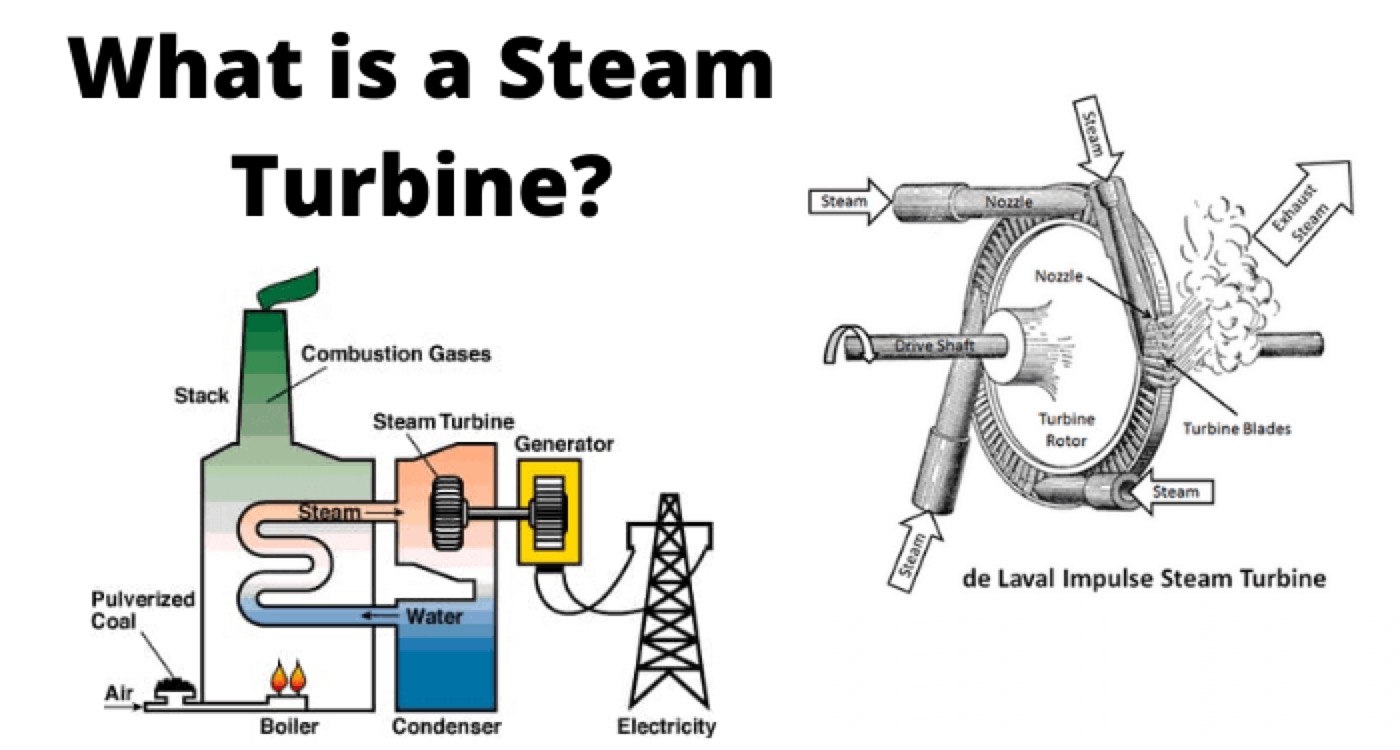
In a steam turbine the steam in the nozzles expands and hence it gains kinetic energy and losses its pressure. The steam gets kinetic energy during its expansion from its internal enthalpy. The blades of turbine obstruct the momentum of the steam and thereby force the stream to change its direction of flow. In other words, the momentum of steam causes a force on the turbine blades. We can say the momentum of expanding steam is the driving force of a steam turbine.
The expansion of steam and changing of direction of momentum may happen once in a single stage or multiple times in various stages depending upon types of turbine.
When there is only one provision of expansion of steam in a turbine and the pressure of steam remains uniform throughout the process after it is expanded through the nozzles, the turbine is called single stage impulse turbine. In impulse turbine high-pressure, high-temperature steam coming out from nozzle head expands and forms a steam jet which directly strikes on the moving blades, causing rotation of the turbine rotor.
There is another type of turbine in which the steam is expanded throughout the process. Here, the expansion of steam takes place when it passes through the turbine blades. During expansion, the enthalpy of steam converts into kinetic energy and thereby the turbine rotor rotates with propeller action.
This type of turbine is referred as reaction turbine. In this type of turbines, there are two sets of blades. One set is of fixed blades attached to the stationary parts of the turbine and another set is of moving blades attached to the rotor of the turbine. The expansion of steam takes place in the space formed by fixed and moving blades.
Normally a practical turbine has two important components nozzles and blades. The nozzle is a device fitted at the steam inlet of a turbine. The high-temperature, high-pressure steam with negligible kinetic energy gets expanded, losses pressure and hence gets sufficient kinetic energy to perform mechanical work with help of the nozzles.
The Blades of the turbines are also referred as deflectors. This is because the dynamics steam gets deflected when it strikes on the blades. The mechanical energy of expanding steam is extracted at turbine blades.
Statement: Respect the original, good articles worth sharing, if there is infringement please contact delete.
We aim to gather electrical knowledge and share it with others.


