What is a Deaerating Heater and How Does It Work?

A deaerating heater, also known as a deaerator, is a device that removes dissolved gases, mainly oxygen, and carbon dioxide, from boiler feedwater. Dissolved gases can cause corrosion and damage to the boiler and its components, as well as reduce the efficiency of the steam cycle. Therefore, deaerating heaters are essential for boiler water treatment and protection.
![]()
Deaerating heaters can be classified into two types: tray type and spray type. Both types use steam to heat the feedwater and strip off the dissolved gases. The steam also acts as a source of oxygen-scavenging chemicals, such as hydrazine or sodium sulfite, that react with the remaining traces of oxygen in the feedwater.
Tray Type Deaerating Heater

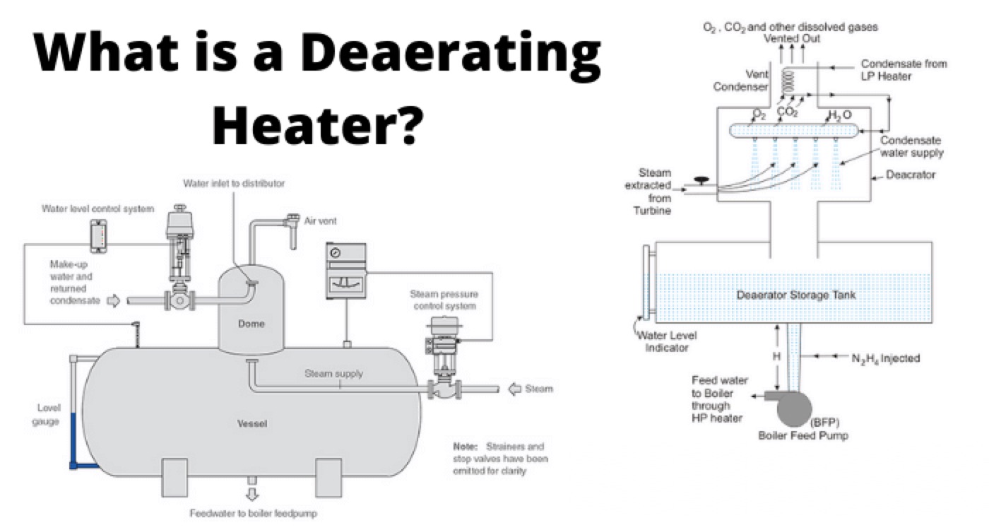
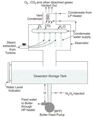
A tray-type deaerating heater consists of a vertical cylindrical vessel with a series of perforated trays inside. The feedwater enters from the top and is sprayed over the trays, creating a thin film of water that flows downward. The steam enters from the bottom and rises upward through the trays, heating the water and removing the dissolved gases. The deaerated water collects at the bottom of the vessel and is pumped to the boiler. The vented gases escape from the top of the vessel.
The advantages of a tray-type deaerating heater are:
It can handle a wide range of feedwater flow rates and temperatures.
It can achieve very low levels of dissolved oxygen (less than 5 ppb) and carbon dioxide (less than 1 ppm).
It has a large storage capacity for feedwater, which helps to maintain constant pressure and temperature in the boiler.
The disadvantages of a tray-type deaerating heater are:
It requires a large amount of steam for deaeration, which reduces the thermal efficiency of the cycle.
It has a high capital cost and maintenance cost due to the complexity and size of the vessel and trays.
It is susceptible to scaling and fouling on the trays, which reduces heat transfer and deaeration efficiency.
Spray Type Deaerating Heater

A spray-type deaerating heater consists of a horizontal cylindrical vessel with a spray nozzle inside. The feedwater enters from one end and is sprayed into a stream of steam that enters from the other end. The steam heats the water and removes the dissolved gases. The deaerated water collects at the bottom of the vessel and is pumped to the boiler. The vented gases escape from the top of the vessel.
The advantages of a spray-type deaerating heater are:
It requires less steam for deaeration than a tray-type deaerating heater, which improves the thermal efficiency of the cycle.
It has a lower capital cost and maintenance cost than a tray-type deaerating heater due to the simplicity and compactness of the vessel and nozzle.
It is less prone to scaling and fouling than a tray-type deaerating heater due to the high velocity and turbulence of the water and steam.
The disadvantages of a spray-type deaerating heater are:
It cannot handle very high or very low feedwater flow rates and temperatures without affecting the deaeration efficiency.
It cannot achieve as low levels of dissolved oxygen (about 10 ppb) and carbon dioxide (about 5 ppm) as a tray-type deaerating heater.
It has a smaller storage capacity for feedwater than a tray-type deaerating heater, which makes it more sensitive to pressure and temperature fluctuations in the boiler.
Factors Affecting Deaeration Efficiency
The efficiency of deaeration depends on several factors, such as:
The temperature and pressure of the feedwater and steam. Higher temperature and lower pressure increase the solubility of gases in water, making it harder to remove them. Therefore, it is important to maintain an optimal temperature difference between the feedwater and steam (usually about 5°C) and an optimal pressure in the deaerating heater (usually about 0.2 bar) and an optimal temperature difference between the feedwater and steam (usually about 5°C).
The amount and quality of steam used for deaeration. The steam should be saturated and free of non-condensable gases. The steam flow rate should be sufficient to provide the required heat and mass transfer for deaeration. The steam flow rate should also be regulated to maintain constant pressure in the deaerating heater.
The design and operation of the deaerating heater. The deaerating heater should have enough surface area and contact time for the feedwater and steam to interact. The feedwater should be sprayed or distributed evenly over the trays or nozzles to create a thin film of water. The deaerating heater should also have a vent condenser to recover the heat and water from the vented gases.
Benefits of Deaerating Heaters
Deaerating heaters provide several benefits for boiler systems, such as:
They prevent corrosion and pitting of boiler tubes, drums, and other components by removing dissolved oxygen and carbon dioxide from the feedwater.
They reduce the chemical oxygen scavenger consumption and cost by minimizing the residual oxygen in the feedwater.
They improve the thermal efficiency of the boiler by preheating the feedwater to near saturation temperature, reducing heat loss and fuel consumption.
They increase the boiler’s reliability and availability by reducing the risk of boiler failures and downtime due to corrosion and scaling.
Conclusion
Deaerating heaters are vital devices for boiler water treatment and protection. They remove dissolved gases from the feedwater using steam as a heating and purging agent. They can be classified into tray type and spray type, depending on their design and configuration. They operate based on the principles of Henry’s Law, Dalton’s Law, and mass and heat transfer. They require optimal conditions of temperature, pressure, and steam flow rate to achieve high deaeration efficiency. They provide several benefits for boiler systems, such as preventing corrosion, reducing chemical consumption, improving thermal efficiency, and increasing reliability.
Statement: Respect the original, good articles worth sharing, if there is infringement please contact delete.
We aim to gather electrical knowledge and share it with others.


