Electronic DC Voltmeter: Definition, Types and Applications


What is a DC Voltage?
A DC voltage is a constant voltage that does not change its polarity or magnitude over time. It is produced by sources such as batteries, solar cells, and DC generators. A DC voltage can be positive or negative depending on the direction of the current flow. A DC voltage can also be converted to an alternating current (AC) voltage by using devices such as inverters and transformers.
How does an Electronic DC Voltmeter Work?
An electronic DC voltmeter works by converting the DC voltage to be measured into a proportional current that can be displayed by a meter movement. The meter movement can be either a permanent magnet moving coil (PMMC) galvanometer or a digital display. The conversion of voltage to current is done by using various electronic components such as resistors, capacitors, diodes, transistors, and amplifiers.
The main components of an electronic DC voltmeter are:
Voltage divider: This is a series of resistors that divides the input voltage into smaller voltage that can be applied to the meter movement. The value of the resistors determines the range and sensitivity of the voltmeter. The voltage divider also provides isolation and protection for the meter movement from high voltages.


Types of Electronic DC Voltmeters
There are different types of electronic DC voltmeters based on their design and functionality. Some of the common types are:
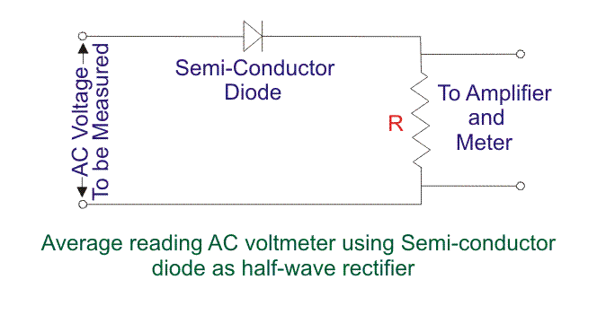
Average reading diode vacuum tube voltmeter: This type of voltmeter uses a vacuum tube diode to rectify the AC voltage into a pulsating DC voltage. The average value of this voltage is measured by a PMMC galvanometer. This type of voltmeter has a simple construction, high input resistance, and low power consumption. However, it has low bandwidth, non-linear operation, and poor accuracy when measuring low voltages.

Applications of Electronic DC Voltmeters
Electronic DC voltmeters are widely used in various fields of science, engineering, and technology for measuring DC voltages. Some of the applications are:
Testing and troubleshooting electronic circuits and devices
Measuring battery voltages and charging levels
Measuring solar panel voltages and power outputs
Measuring sensor outputs and signal levels
Measuring electrostatic potentials and fields
Measuring bioelectric potentials and signals
Conclusion
An electronic DC voltmeter is a device that measures the direct current (DC) voltage across any two points of an electric circuit. It uses semiconductor components such as diodes, transistors, and amplifiers to increase its sensitivity and accuracy. There are different types of electronic DC voltmeters based on their design and functionality, such as average reading diode vacuum tube voltmeter, peak reading diode vacuum tube voltmeter, difference amplifier type electronic voltmeter, and digital multimeter. Electronic DC voltmeters have various applications in testing, troubleshooting, and designing electronic circuits and devices. They can measure DC voltages from microvolts to kilovolts with high precision and speed. They are essential tools for electrical and electronic engineers, technicians, and hobbyists.
Statement: Respect the original, good articles worth sharing, if there is infringement please contact delete.
Electrical4U is dedicated to the teaching and sharing of all things related to electrical and electronics engineering.


